Modern vehicle diagnostics often rely heavily on digital scan tools, but the most profound electrical failures frequently stem from a fundamental mechanical breakdown: the loss of a clean ground path. In the realm of high-stakes auto repair, a compromised ground wire acts as a silent disruptor, sending erratic signals to the Transmission Control Module (TCM) and triggering phantom fault codes that can lead even seasoned technicians down a rabbit hole of unnecessary parts replacement. Achieving a reliable car service outcome requires looking past the software and inspecting the physical integrity of the vehicle’s electrical foundation. [image_placeholder]
The Invisible Saboteur of Modern Transmission Controls
When a ground wire degrades, the electrical current seeks the path of least resistance, which often involves back-feeding through sensitive sensors or shift solenoids. This phenomenon can cause unexpected transmission failures that mimic mechanical wear. Professional-grade vehicle diagnostics start by recognizing that electrical ‘noise’ is usually a physical grounding issue. If you notice your gearbox hunting for gears or shifting harshly specifically when high-draw components like headlights or the blower motor are active, you are likely dealing with a ground-loop interference rather than a failing clutch pack. This is why integrated car service protocols must always include a visual and tactile inspection of the chassis-to-engine bonding straps before any components are condemned.
Could Your Engine Block Be Starving for a Proper Path to Ground?
A common query in master technician forums involves why a vehicle might start perfectly one day and fail the next without a battery voltage drop. The answer often lies in the engine-to-chassis ground strap. You can spot a bad ground wire by performing a ‘load-based’ visual test using the vehicle’s own high-amperage components. Turn on the high beams and attempt to crank the engine; if the lights extinguish completely rather than merely dimming, the resistance in the ground circuit is likely too high to support the starter’s amperage draw. This is a critical diagnostic step to perform before committing to expensive auto repair for intermittent starting issues.
Physical Stress Tests for Corroded Ground Straps
Without a multimeter, your primary diagnostic tools are heat, light, and tactile feedback. A grounding point that has high resistance will generate significant thermal energy due to the energy being dissipated across the corrosion. After a short drive where you have operated heavy electrical loads, carefully feel the ground terminals (being mindful of moving parts and hot surfaces). A terminal that is hot to the touch is a definitive sign of internal corrosion or a loose connection that is choking the system. Furthermore, the ‘wobble test’ on the main negative cable can reveal internal wire fatigue where the copper meets the lead terminal. If you find yourself constantly resetting electronics, it is time to unlock your car’s potential by refreshing these basic connections. For a deeper dive into the physics of automotive grounding, the Society of Automotive Engineers (SAE) provides extensive documentation on electrical grounding standards for heavy-duty vehicle systems.
Don’t Let Ghost Codes Drain Your Wallet
If you are struggling with erratic sensor readings that defy logic, consider contributing your findings to our professional community or browse our guide on the hidden world of vehicle diagnostics to see how ground integrity impacts overall system health and longevity.
Why Your Transmission Hesitates Despite Clean Fluid
When drivers experience a noticeable pause between shifting from reverse to drive, their immediate instinct is to check the dipstick. However, many find that fixing the common delay when shifting from reverse to drive often has nothing to do with fluid levels and everything to do with solenoid voltage. Modern automatic transmissions rely on electronic solenoids to direct hydraulic pressure. If a ground wire is frayed or corroded, these solenoids cannot receive the full amperage required to actuate quickly. This results in a ‘soft’ engagement or a jarring thud as the computer tries to compensate for the delayed response. Before assuming your clutch packs are burnt, verify that the transmission case itself has a clean path to the negative battery terminal.
Is Your Dashboard Acting Like a Strobe Light on Rough Roads?
If you notice that your dashboard lights flicker every time you hit a pothole, you aren’t just dealing with a loose bulb or a failing battery. In high-tech multiplexed wiring systems, a momentary interruption in ground connectivity can cause the entire Controller Area Network (CAN-bus) to flicker or reset. This creates a cascade of ‘communication lost’ fault codes that can lead a technician to believe multiple modules have failed simultaneously. The physical vibration of a bump causes a loose grounding lug to vibrate, breaking the circuit for a fraction of a second. Instead of replacing expensive electronics, check the main ground points located behind the battery tray or near the strut towers; a simple cleaning of the mating surface can resolve what looks like a terminal failure.

Stop Chasing Ghost Sensors and Check the Negative Terminal
A compromised ground path doesn’t just kill the starter; it skews the signal data for every sensor on the engine. For instance, the Mass Air Flow (MAF) sensor operates on an extremely sensitive millivolt scale. If the reference ground is offset by even 0.3 volts due to oxidation at the engine block, the ECU will receive inaccurate data about air intake. This leads to a lean-running condition that triggers a check engine light for ‘System Lean’ rather than a sensor failure. Before you learn how to clean a mass air flow sensor without damaging the hot wire, ensure the sensor’s ground circuit isn’t floating. Leading automotive component manufacturers like Bosch Mobility note that sensor reliability is strictly tied to a stable voltage environment, where even minute resistance in the ground path can lead to significant fuel trim errors. This is frequently the one sensor that ruins your gas mileage without triggering a warning light until the ground failure becomes catastrophic.
What Happens When the TCM Loses Its Reference Voltage?
The Transmission Control Module (TCM) is highly susceptible to electrical interference. When the grounding strap between the engine and chassis degrades, the TCM may struggle to calculate shift timing, leading to instances where your transmission shifts hard only between second and third. This isn’t a mechanical flaw but a safety protocol; the computer ‘slams’ the gear to prevent internal slippage when it cannot confirm the precise solenoid position. Utilizing a 20 dollar scan tool that finds hidden transmission codes can help you identify ‘Low Voltage’ or ‘Reference Circuit Range’ errors that point directly to the electrical foundation rather than the gearbox internals. If you have encountered a strange electrical ‘ghost’ that fixed itself after a simple cleaning, share your story in the comments—your insight might save another car owner from an unnecessary transmission rebuild.
Why a Multimeter Beats a Visual Check Every Time
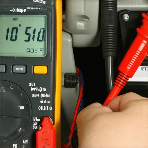
While visual inspections catch obvious green corrosion, the most insidious ground failures occur deep within the crimp of the terminal itself. This is where a digital multimeter becomes your most trusted ally in vehicle diagnostics. By performing a voltage drop test—measuring the potential difference between the battery’s negative post and the engine block while the starter is cranking—you reveal the invisible resistance that standard continuity tests miss. A reading higher than 0.2 volts indicates that your ground path is essentially a bottleneck, forcing the electrical system to work overtime and generating heat that eventually melts insulation or fries sensitive ECU drivers.
Stop Killing Your Alternator with High-Resistance Ground Loops
An often-overlooked consequence of a failing ground strap is the unnecessary stress placed on the charging system. When the path back to the battery is restricted, the alternator must increase its output voltage to overcome the resistance, leading to premature regulator failure and ‘whining’ noises that many mistake for a mechanical bearing issue. This is why a comprehensive car service should always include a check of the alternator-to-engine mounting bolts. If these bolts are oxidized, the alternator’s own ground is compromised, creating a ‘dirty’ DC signal that can confuse the TCM and cause the transmission to hunt for gears or fail to engage overdrive.
Why does my car struggle to crank only when the engine is hot?
This phenomenon, often mistaken for a ‘heat-soaked’ starter, is frequently caused by the increased resistance of a degrading ground wire when exposed to engine bay temperatures. Metals conduct less efficiently as they heat up; a ground strap that barely functions at 70°F may fail entirely at 200°F after a long drive. This specific failure mode is a prime example of why intermittent auto repair issues are so difficult to pin down. For those looking to master these nuances, the technical training resources at DENSO provide a deep dive into how high-temperature environments affect sensor grounding and signal integrity, particularly in oxygen sensors.
How a Rusted Bolt Tricks Your Oxygen Sensor into Burning Extra Fuel
Grounding issues don’t just affect power; they corrupt the very data your engine uses to stay efficient. Oxygen (O2) sensors generate their own tiny voltage signal, usually between 0.1 and 0.9 volts. If the engine block ground is ‘biased’ by just 0.2 volts due to a rusted mounting bolt, the ECU sees a skewed signal. It may interpret a perfectly balanced air-fuel ratio as ‘lean’ and dump excess fuel into the cylinders to compensate. This not only ruins your gas mileage but can lead to carbon buildup that eventually kills your catalytic converter. Before you spend hundreds on new sensors, unlock your car’s potential by ensuring the sensor’s reference ground is absolute zero. When you analyze the fuel trim data on your scan tool, a ‘floating ground’ at the O2 sensor often manifests as…
…a floating ground at the O2 sensor often manifests as a slow-reacting signal that confuses the ECU’s fuel trim logic, leading to a rich condition that fouls spark plugs and accelerates catalytic converter wear. But the impact of a compromised ground path extends far beyond fuel economy into the sophisticated safety systems of modern vehicles.
Why Modern Driver-Assist Systems Fail on Weak Grounds
In the current era of Advanced Driver Assistance Systems (ADAS), a stable ground is no longer just about completing a circuit—it is about maintaining signal integrity for high-speed data. Components like Radar sensors and Lane Departure cameras rely on a clean reference potential to distinguish between a valid signal and background noise. When a ground wire develops high resistance, the signal-to-noise ratio degrades. This is why you might experience a ‘Service ADAS’ light that disappears when the car is cold but returns after the engine bay heats up. Professionals performing high-stakes vehicle diagnostics understand that the digital ‘0’ and ‘1’ of a CAN-bus signal require a stable ground floor to prevent bit-errors that shut down safety features.
Can a Wet Engine Connector Corrupt Your Entire Data Network?
The short answer is yes. Beyond mere corrosion, a phenomenon known as ‘capillary action’ or ‘wicking’ presents a nightmare scenario for modern auto repair. If a sensor—such as the oil pressure switch or a coolant temperature sensor—leaks internally, the fluid can be pushed by pressure through the individual copper strands of the wire. This fluid acts as a bridge, carrying contaminants and altering the resistance of the ground path. Eventually, this oil or coolant reaches the Engine Control Unit (ECU) pins, causing phantom shorts. For technicians, checking for ‘wet’ pins at the ECU is a vital diagnostic step when dealing with a car that throws dozens of unrelated sensor codes simultaneously.

The Physical Layer: Measuring CAN-bus Ground Offsets
When the Transmission Control Module (TCM) loses its common ground with the main ECU, the differential voltage on the CAN-bus lines (CAN-High and CAN-Low) can shift out of the acceptable ‘recessive’ and ‘dominant’ state ranges. This doesn’t just cause a hard shift; it can put the vehicle into ‘Limp Mode’ to protect the drivetrain. According to the experts at Hella Tech World, many network communication failures are physical layer issues—meaning the wiring or grounding is at fault, not the computer itself. Using an oscilloscope to view the ‘square wave’ of the data stream can reveal if the ground plane is ‘floating,’ which causes the signal to look jagged and distorted rather than clean and crisp.
Shielded Cables and the Battle Against Electromagnetic Interference
High-frequency components like the Crankshaft Position Sensor often use shielded cables to prevent interference from the ignition system. The shield itself must be grounded at only one end to prevent a ‘ground loop’—a circular current path that actually creates more noise. If a previous mechanic incorrectly grounded both ends of a replacement harness, the resulting interference can make a perfectly good engine misfire or stall under load. This level of transmission failure or engine stalling is often misdiagnosed as a faulty sensor, when the reality is a fundamental violation of grounding physics. If you’ve discovered oil inside your ECU connector or encountered a stubborn U-code, share your findings in our community—identifying these wicking issues early can save thousands in module replacements.
Modern vehicle diagnostics often rely heavily on digital scan tools, but the most profound electrical failures frequently stem from a fundamental mechanical breakdown: the loss of a clean ground path. In the realm of high-stakes auto repair, a compromised ground wire acts as a silent disruptor, sending erratic signals to the Transmission Control Module (TCM) and triggering phantom fault codes that can lead even seasoned technicians down a rabbit hole of unnecessary parts replacement. Achieving a reliable car service outcome requires looking past the software and inspecting the physical integrity of the vehicle’s electrical foundation. [image_placeholder]
The Invisible Saboteur of Modern Transmission Controls
When a ground wire degrades, the electrical current seeks the path of least resistance, which often involves back-feeding through sensitive sensors or shift solenoids. This phenomenon can cause unexpected transmission failures that mimic mechanical wear. Professional-grade vehicle diagnostics start by recognizing that electrical ‘noise’ is usually a physical grounding issue. If you notice your gearbox hunting for gears or shifting harshly specifically when high-draw components like headlights or the blower motor are active, you are likely dealing with a ground-loop interference rather than a failing clutch pack. This is why integrated car service protocols must always include a visual and tactile inspection of the chassis-to-engine bonding straps before any components are condemned.
Could Your Engine Block Be Starving for a Proper Path to Ground?
A common query in master technician forums involves why a vehicle might start perfectly one day and fail the next without a battery voltage drop. The answer often lies in the engine-to-chassis ground strap. You can spot a bad ground wire by performing a ‘load-based’ visual test using the vehicle’s own high-amperage components. Turn on the high beams and attempt to crank the engine; if the lights extinguish completely rather than merely dimming, the resistance in the ground circuit is likely too high to support the starter’s amperage draw. This is a critical diagnostic step to perform before committing to expensive auto repair for intermittent starting issues.
Physical Stress Tests for Corroded Ground Straps
Without a multimeter, your primary diagnostic tools are heat, light, and tactile feedback. A grounding point that has high resistance will generate significant thermal energy due to the energy being dissipated across the corrosion. After a short drive where you have operated heavy electrical loads, carefully feel the ground terminals (being mindful of moving parts and hot surfaces). A terminal that is hot to the touch is a definitive sign of internal corrosion or a loose connection that is choking the system. Furthermore, the ‘wobble test’ on the main negative cable can reveal internal wire fatigue where the copper meets the lead terminal. If you find yourself constantly resetting electronics, it is time to unlock your car’s potential by refreshing these basic connections. For a deeper dive into the physics of automotive grounding, the Society of Automotive Engineers (SAE) provides extensive documentation on electrical grounding standards for heavy-duty vehicle systems.
Don’t Let Ghost Codes Drain Your Wallet
If you are struggling with erratic sensor readings that defy logic, consider contributing your findings to our professional community or browse our guide on the hidden world of vehicle diagnostics to see how ground integrity impacts overall system health and longevity.
Why Your Transmission Hesitates Despite Clean Fluid
When drivers experience a noticeable pause between shifting from reverse to drive, their immediate instinct is to check the dipstick. However, many find that fixing the common delay when shifting from reverse to drive often has nothing to do with fluid levels and everything to do with solenoid voltage. Modern automatic transmissions rely on electronic solenoids to direct hydraulic pressure. If a ground wire is frayed or corroded, these solenoids cannot receive the full amperage required to actuate quickly. This results in a ‘soft’ engagement or a jarring thud as the computer tries to compensate for the delayed response. Before assuming your clutch packs are burnt, verify that the transmission case itself has a clean path to the negative battery terminal.
Is Your Dashboard Acting Like a Strobe Light on Rough Roads?
If you notice that your dashboard lights flicker every time you hit a pothole, you aren’t just dealing with a loose bulb or a failing battery. In high-tech multiplexed wiring systems, a momentary interruption in ground connectivity can cause the entire Controller Area Network (CAN-bus) to flicker or reset. This creates a cascade of ‘communication lost’ fault codes that can lead a technician to believe multiple modules have failed simultaneously. The physical vibration of a bump causes a loose grounding lug to vibrate, breaking the circuit for a fraction of a second. Instead of replacing expensive electronics, check the main ground points located behind the battery tray or near the strut towers; a simple cleaning of the mating surface can resolve what looks like a terminal failure.
Stop Chasing Ghost Sensors and Check the Negative Terminal
A compromised ground path doesn’t just kill the starter; it skews the signal data for every sensor on the engine. For instance, the Mass Air Flow (MAF) sensor operates on an extremely sensitive millivolt scale. If the reference ground is offset by even 0.3 volts due to oxidation at the engine block, the ECU will receive inaccurate data about air intake. This leads to a lean-running condition that triggers a check engine light for ‘System Lean’ rather than a sensor failure. Before you learn how to clean a mass air flow sensor without damaging the hot wire, ensure the sensor’s ground circuit isn’t floating. Leading automotive component manufacturers like Bosch Mobility note that sensor reliability is strictly tied to a stable voltage environment, where even minute resistance in the ground path can lead to significant fuel trim errors. This is frequently the one sensor that ruins your gas mileage without triggering a warning light until the ground failure becomes catastrophic.
What Happens When the TCM Loses Its Reference Voltage?
The Transmission Control Module (TCM) is highly susceptible to electrical interference. When the grounding strap between the engine and chassis degrades, the TCM may struggle to calculate shift timing, leading to instances where your transmission shifts hard only between second and third. This isn’t a mechanical flaw but a safety protocol; the computer ‘slams’ the gear to prevent internal slippage when it cannot confirm the precise solenoid position. Utilizing a 20 dollar scan tool that finds hidden transmission codes can help you identify ‘Low Voltage’ or ‘Reference Circuit Range’ errors that point directly to the electrical foundation rather than the gearbox internals. If you have encountered a strange electrical ‘ghost’ that fixed itself after a simple cleaning, share your story in the comments—your insight might save another car owner from an unnecessary transmission rebuild.
Why a Multimeter Beats a Visual Check Every Time
While visual inspections catch obvious green corrosion, the most insidious ground failures occur deep within the crimp of the terminal itself. This is where a digital multimeter becomes your most trusted ally in vehicle diagnostics. By performing a voltage drop test—measuring the potential difference between the battery’s negative post and the engine block while the starter is cranking—you reveal the invisible resistance that standard continuity tests miss. A reading higher than 0.2 volts indicates that your ground path is essentially a bottleneck, forcing the electrical system to work overtime and generating heat that eventually melts insulation or fries sensitive ECU drivers.
Stop Killing Your Alternator with High-Resistance Ground Loops
An often-overlooked consequence of a failing ground strap is the unnecessary stress placed on the charging system. When the path back to the battery is restricted, the alternator must increase its output voltage to overcome the resistance, leading to premature regulator failure and ‘whining’ noises that many mistake for a mechanical bearing issue. This is why a comprehensive car service should always include a check of the alternator-to-engine mounting bolts. If these bolts are oxidized, the alternator’s own ground is compromised, creating a ‘dirty’ DC signal that can confuse the TCM and cause the transmission to hunt for gears or fail to engage overdrive.
Why does my car struggle to crank only when the engine is hot?
This phenomenon, often mistaken for a ‘heat-soaked’ starter, is frequently caused by the increased resistance of a degrading ground wire when exposed to engine bay temperatures. Metals conduct less efficiently as they heat up; a ground strap that barely functions at 70°F may fail entirely at 200°F after a long drive. This specific failure mode is a prime example of why intermittent auto repair issues are so difficult to pin down. For those looking to master these nuances, the technical training resources at DENSO provide a deep dive into how high-temperature environments affect sensor grounding and signal integrity, particularly in oxygen sensors.
How a Rusted Bolt Tricks Your Oxygen Sensor into Burning Extra Fuel
Grounding issues don’t just affect power; they corrupt the very data your engine uses to stay efficient. Oxygen (O2) sensors generate their own tiny voltage signal, usually between 0.1 and 0.9 volts. If the engine block ground is ‘biased’ by just 0.2 volts due to a rusted mounting bolt, the ECU sees a skewed signal. It may interpret a perfectly balanced air-fuel ratio as ‘lean’ and dump excess fuel into the cylinders to compensate. This not only ruins your gas mileage but can lead to carbon buildup that eventually kills your catalytic converter. Before you spend hundreds on new sensors, unlock your car’s potential by ensuring the sensor’s reference ground is absolute zero. When you analyze the fuel trim data on your scan tool, a ‘floating ground’ at the O2 sensor often manifests as a slow-reacting signal that confuses the ECU’s fuel trim logic, leading to a rich condition that fouls spark plugs and accelerates catalytic converter wear. But the impact of a compromised ground path extends far beyond fuel economy into the sophisticated safety systems of modern vehicles.
Why Modern Driver-Assist Systems Fail on Weak Grounds
In the current era of Advanced Driver Assistance Systems (ADAS), a stable ground is no longer just about completing a circuit—it is about maintaining signal integrity for high-speed data. Components like Radar sensors and Lane Departure cameras rely on a clean reference potential to distinguish between a valid signal and background noise. When a ground wire develops high resistance, the signal-to-noise ratio degrades. This is why you might experience a ‘Service ADAS’ light that disappears when the car is cold but returns after the engine bay heats up. Professionals performing high-stakes vehicle diagnostics understand that the digital ‘0’ and ‘1’ of a CAN-bus signal require a stable ground floor to prevent bit-errors that shut down safety features.
Can a Wet Engine Connector Corrupt Your Entire Data Network?
The short answer is yes. Beyond mere corrosion, a phenomenon known as ‘capillary action’ or ‘wicking’ presents a nightmare scenario for modern auto repair. If a sensor—such as the oil pressure switch or a coolant temperature sensor—leaks internally, the fluid can be pushed by pressure through the individual copper strands of the wire. This fluid acts as a bridge, carrying contaminants and altering the resistance of the ground path. Eventually, this oil or coolant reaches the Engine Control Unit (ECU) pins, causing phantom shorts. For technicians, checking for ‘wet’ pins at the ECU is a vital diagnostic step when dealing with a car that throws dozens of unrelated sensor codes simultaneously.
The Physical Layer: Measuring CAN-bus Ground Offsets
When the Transmission Control Module (TCM) loses its common ground with the main ECU, the differential voltage on the CAN-bus lines (CAN-High and CAN-Low) can shift out of the acceptable ‘recessive’ and ‘dominant’ state ranges. This doesn’t just cause a hard shift; it can put the vehicle into ‘Limp Mode’ to protect the drivetrain. According to the experts at Hella Tech World, many network communication failures are physical layer issues—meaning the wiring or grounding is at fault, not the computer itself. Using an oscilloscope to view the ‘square wave’ of the data stream can reveal if the ground plane is ‘floating,’ which causes the signal to look jagged and distorted rather than clean and crisp.
Shielded Cables and the Battle Against Electromagnetic Interference
High-frequency components like the Crankshaft Position Sensor often use shielded cables to prevent interference from the ignition system. The shield itself must be grounded at only one end to prevent a ‘ground loop’—a circular current path that actually creates more noise. If a previous mechanic incorrectly grounded both ends of a replacement harness, the resulting interference can make a perfectly good engine misfire or stall under load. This level of transmission failure or engine stalling is often misdiagnosed as a faulty sensor, when the reality is a fundamental violation of grounding physics.
Expert Insights & Advanced Considerations
Thermal Imaging Reveals What the Multimeter Misses
While a multimeter is essential, it only measures a specific point in time. For technicians performing advanced auto repair techniques, a thermal camera can identify high-resistance ground points instantly by visualizing the heat signatures of “choke points” where current is struggling to pass through corroded strands.
The Silver Solder Advantage in High-Vibration Harnesses
In performance applications or heavy-duty environments, standard crimping is often insufficient. Experts prioritize silver-bearing solder for ground terminations to prevent the microscopic fretting corrosion that causes intermittent connectivity issues. This attention to detail is what separates a standard repair from a high-tier car service.
Stop Treating the Symptoms of CAN-bus Noise
If you are repeatedly replacing modules for communication errors, you aren’t solving the underlying problem. Network stability is entirely dependent on a “clean” ground. Always check the continuity between the ECU case and the negative terminal before condemning a processor; a 0.5-ohm difference can be the difference between a functional car and a total electronic failure.
Curated Expert Resources
I-ATN (International Automotive Technicians Network)
A premier global community where master technicians share real-world telemetry and case studies on complex electrical failures that defy standard diagnostic trees.
AESwave Diagnostic Tools
The gold standard for acquiring specialized lab scopes and current probes necessary for high-level vehicle diagnostics and waveform analysis.
ScannerDanner Premium Curriculum
An exhaustive educational resource for mastering the physics behind voltage drop testing and advanced engine performance analytics.
Final Expert Perspective
True automotive mastery is found in the physical layer of the vehicle. By shifting focus from digital fault codes back to the integrity of the chassis-to-engine ground, you eliminate the “ghosts” that haunt modern drivetrains. A comprehensive car service should always treat the electrical foundation as a mechanical component subject to wear and environmental decay. If you’ve successfully tracked down a hidden electrical drain or resolved a complex transmission trouble through grounding, your expertise is invaluable—share your process below to help the community move past the “parts cannon” approach to repair.