Why a Dirty Platinum Wire Sabotages Your Engine’s Brain
The Mass Air Flow (MAF) sensor is the primary sensory organ for the modern internal combustion engine, responsible for measuring the mass of air entering the intake manifold. Unlike simple volumetric measurements, the MAF utilizes a heated platinum wire—maintained at a precise temperature above ambient air—to calculate density through current draw. When microscopic debris or oil film coats this wire, it creates a thermal insulator, causing the sensor to report less air than is actually present. This results in a ‘lean’ calculation that forces the ECU to adjust fuel trims incorrectly, often causing a rough idle and significant power loss. According to technical standards established by entities like Bosch, even a microscopic layer of contamination can alter voltage output enough to knock an engine out of its optimal closed-loop operation and stoichiometric balance.
Stop Reaching for Carb Cleaner: The Chemistry of Sensor Safety
The most common error in auto repair is the use of aggressive solvents like chlorinated brake cleaners or carburetor sprays on MAF sensors. These chemicals are designed to strip heavy carbon deposits but are far too caustic for the delicate bonding agents used in sensor housing. Using the wrong solvent can lead to the ‘cold-start stumble’ or even permanent circuit failure via thermal shock. For those performing a wider car service, it is imperative to use only dedicated MAF cleaner, which evaporates instantly without leaving a petroleum-based residue that would otherwise attract more dust. If you are already inspecting the intake, it is also a wise time to learn the best way to clean your engine bay without damaging sensors to prevent external contaminants from migrating into the intake tract.
Can a Fouled Sensor Mimic a Dying Transmission?
In many modern vehicles, the Transmission Control Module (TCM) relies heavily on the load data provided by the MAF sensor to determine line pressure and shift timing. A contaminated sensor often leads to ‘soft’ shifts, erratic gear hunting, or delayed engagement, which many drivers mistake for catastrophic transmission failures. Before committing to expensive gearbox teardowns, performing high-level vehicle diagnostics to verify MAF grams-per-second (g/s) at idle and wide-open throttle can save thousands in unnecessary repairs. If your vehicle feels sluggish or confused during acceleration, it is often the main reason your car hesitates rather than a mechanical hardware failure in the drivetrain.
The Surgical Approach to Wire Restoration
To clean the sensor safely, remove the housing from the intake ducting, taking care not to drop the unit—the internal ceramic substrate is highly brittle and sensitive to vibration. Use short, controlled bursts of MAF cleaner from a distance of 4 to 6 inches, targeting the tiny wire suspended in the center of the air stream. Never, under any circumstances, use a cotton swab or brush on the hot wire itself; the physical contact will almost certainly snap the bridge. Allow the unit to air dry for at least 15 minutes to ensure all solvent has evaporated from the internal circuitry before re-energizing the system. Advanced technicians often monitor the ‘Long Term Fuel Trim’ after a cleaning procedure; if the values return toward 0% from a high positive percentage, the cleaning was successful. This level of scrutiny distinguishes a professional expert auto repair from basic part-swapping. If your hesitation persists even after cleaning, it’s time to perform a deeper dive into the hidden world of vehicle diagnostics to identify upstream air leaks or faulty manifold absolute pressure sensors.
Don’t Guess When You Can Measure with Live Data
While physical cleaning is a vital first step, modern diagnostic precision requires looking at the data stream. Professional technicians utilize the ‘Grams per Second’ (g/s) metric on a scan tool to verify sensor integrity without even popping the hood. A generally accepted rule of professional vehicle diagnostics is that a healthy engine should show approximately 1 gram per second for every liter of engine displacement at idle. If your 3.5L V6 is reporting only 1.8 g/s, the sensor is ‘under-reporting,’ likely due to residual film or internal component degradation. This subtle inaccuracy is often why your engine starts then immediately dies during cold enrichment phases, as the computer fails to provide enough fuel for the actual volume of air entering the cylinders.
Is Your Performance Air Filter Actually Coating Your Platinum Wire in Oil?
One of the most overlooked sources of MAF contamination is the improper maintenance of high-flow ‘wet’ air filters. While these components offer improved airflow, the oil used to trap particulates can easily atomize and migrate downstream if over-applied. This aerosolized oil bakes onto the platinum sensing element, creating a permanent insulating barrier that cleaning sprays may struggle to fully penetrate. According to research published by SAE International, even a microscopic deviation in the thermistor’s surface temperature can lead to a 10-15% error in fuel delivery calculations. If you find yourself cleaning the sensor every few months, it may be time to use the 30-tool that lets you see inside your engine or intake tract to check for heavy oil pooling that signals an over-serviced filter or a failing PCV system.
Spot the Ghost Air That Tricks Your Sensor
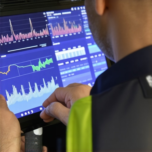
Even a perfectly clean MAF sensor cannot compensate for ‘unmetered air’—leaks that occur between the sensor housing and the intake manifold. When air enters through a cracked vacuum line or a loose intake boot, the sensor never ‘sees’ it, but the oxygen sensors in the exhaust certainly do. This creates a confusing data loop where the ECU sees a lean condition and adds fuel, while the MAF reports low load. This discrepancy is a hallmark of complex transmission failures and shifting glitches because the computer cannot calculate the torque load accurately. Utilizing the 12-tool that finds every vacuum leak in minutes is the only way to ensure the air being measured by the MAF is the only air the engine is actually consuming.
The Aftermarket Trap and Voltage Calibration
When cleaning fails, the temptation to buy a cheap, no-name replacement sensor is high. However, the MAF sensor is a precision instrument calibrated to a specific voltage-to-airflow curve. Low-quality aftermarket sensors often use inferior thermistors that do not react quickly enough to rapid throttle changes, leading to the very hesitation issues you were trying to solve. If your car still stumbles after a replacement, you may be dealing with the main reason your car hesitates: a slow-responding sensor. Always cross-reference your live data against OEM specifications to ensure the signal remains within the tight tolerances required for modern emissions standards. Have you ever cleared a persistent ‘System Lean’ code only to have it return a week later? Share your diagnostic journey in the comments below, or read our guide on how to clean your mass air flow sensor to fix a rough idle to see if you missed a crucial step in the restoration process.
Fix the Ground Before Junking a Functional Sensor
Many technicians rush to replace a sensor when the voltage seems erratic, but the issue often lies in high resistance within the wiring harness. The MAF sensor is incredibly sensitive to electrical ‘noise’ and grounding issues. If the reference ground shared with other sensors becomes compromised, the MAF signal can ‘float,’ providing the ECU with a jagged voltage wave that causes erratic fuel delivery. This is why high-level vehicle diagnostics involve back-probing the connector with a multimeter to ensure the voltage drop across the ground circuit is less than 0.1 volts. A poor ground is often the culprit behind a phantom rough idle that returns even after the sensor is cleaned or replaced. Expert mechanics know that the sensor is only as good as the circuit it sits on, and neglecting the harness is a recipe for expensive, unnecessary part-swapping.
Why Does My Engine Run Better on Crisp Autumn Mornings?
Drivers often notice their car feels more responsive in cool, dry weather, and this isn’t just a psychological trick—it’s physics interacting with your MAF. Humidity actually decreases the density of the air; contrary to popular belief, moist air is less dense than dry air because water vapor molecules are lighter than nitrogen and oxygen molecules. A MAF sensor must work harder to calculate the cooling effect of this less-dense, humid air. While the sensor is designed to compensate for these variables, extreme humidity can sometimes cause ‘signal drift’ where the sensor slightly miscalculates the air mass. If you notice your car struggling specifically during heavy rain or high humidity, it may be time to investigate the main reason your car hesitates: a sensor that is physically clean but failing its internal resistance tests for environmental compensation.
The Invisible War Between MAF Data and Oxygen Sensor Feedback
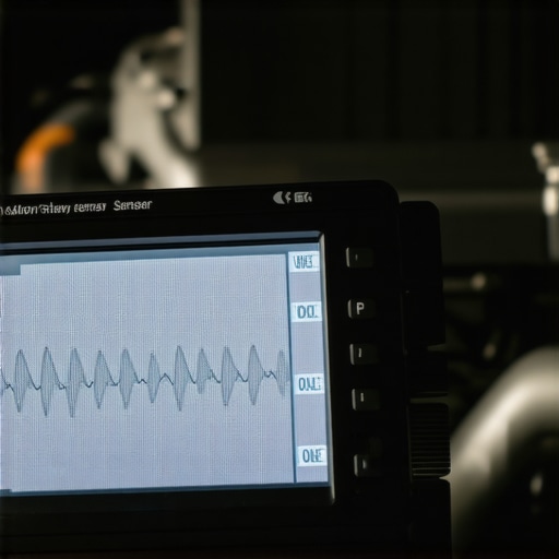
The ECU operates in a constant state of skepticism, using the Oxygen (O2) sensors to ‘fact-check’ what the MAF sensor is reporting. This is known as the closed-loop feedback system. If the MAF says there is 5 grams of air entering, but the O2 sensor detects too much unburned oxygen in the exhaust, the ECU assumes the MAF is lying or there is a leak. It then applies a ‘Fuel Trim’ correction to add more fuel. When these corrections exceed 10-15%, you’ll see a Check Engine Light. This discrepancy is a primary driver of transmission failures in late-model vehicles, as the TCM cannot accurately predict the torque required for a smooth shift if the engine’s load data is fluctuating. For a more comprehensive look at how these systems interact, you should check out top auto repair techniques that focus on fuel trim analysis rather than just reading trouble codes.
How Digital MAF Sensors Revolutionized Fuel Accuracy
Older MAF sensors utilized an analog 0-5V signal, which was highly susceptible to interference from spark plug wires or the alternator. Modern vehicles have largely transitioned to digital frequency-based sensors. Instead of changing voltage, these sensors output a square wave frequency (measured in Hertz) to represent airflow. According to technical documentation from Delphi Technologies, digital signals are significantly more robust against electrical interference, allowing the ECU to make fuel adjustments with microsecond precision. This shift is critical because it allows for tighter emissions control and better fuel economy. However, diagnosing a digital sensor requires an oscilloscope rather than a simple voltmeter, as a standard multimeter cannot see the ‘drop-outs’ in a high-frequency square wave. If your car is suffering from a mysterious stumble under load, exploring the hidden world of vehicle diagnostics with a scope can reveal signal glitches that a standard scanner would completely miss.
The Thermal Inertia of Modern Hot-Film Designs
While the older ‘hot wire’ sensors were prone to breaking, modern ‘hot-film’ sensors are much more durable but face a different challenge: thermal inertia. The film must heat up and cool down almost instantly to track the pulses of air created by the opening and closing of intake valves. As these sensors age, the film can become ‘sluggish,’ failing to respond to rapid changes in throttle position. This delay causes a momentary lean condition during acceleration, which is often the silent catalyst behind an engine that starts then immediately dies or stumbles during a quick lane change. Understanding this response time is vital for any expert auto repair professional. If you have already performed a thorough cleaning and checked for vacuum leaks, the next step involves analyzing the ‘Alpha-N’ fail-safe mode of your ECU to see how it reacts when the MAF signal is disconnected—a classic trick to isolate a failing sensor from a mechanical air leak.
Why Your Aftermarket Electronics Could Be Stealthily Sabotaging Your Signal
In the pursuit of modern customization, many enthusiasts inadvertently introduce electromagnetic interference (EMI) that wreaks havoc on sensitive engine sensors. The Mass Air Flow sensor operates on a low-voltage millivolt scale, making it extremely susceptible to electrical ‘noise’ generated by poorly shielded HID ballasts, high-output alternators, or even incorrectly routed spark plug wires. If these components are located too close to the MAF wiring harness, they can induce a ‘ghost’ voltage that shifts the sensor’s output curve. This subtle deviation is often the main reason your car hesitates during sudden acceleration, as the ECU receives a jumbled signal that doesn’t match the physical throttle opening. Professional grade vehicle diagnostics require the use of a shielded lead or an oscilloscope to detect these high-frequency ripples that a standard digital multimeter simply cannot capture.
The Secret Life of the Integrated Intake Air Temperature Thermistor
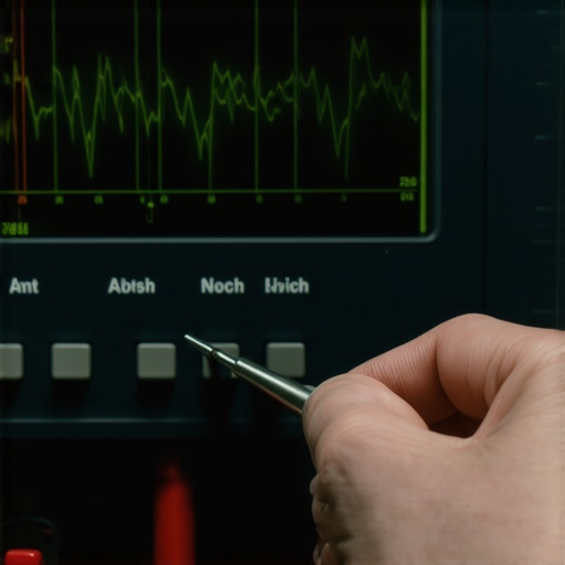
Most modern MAF assemblies are actually dual-purpose instruments, housing the Intake Air Temperature (IAT) sensor within the same plastic body. While we focus heavily on the platinum hot-wire, the IAT is equally critical for determining air density. If the IAT portion of the sensor becomes skewed due to heat soak or internal resistance, it may report an intake temperature of 140°F when the actual ambient air is 60°F. Since colder air is denser and requires more fuel, this ‘warm’ false reading forces the ECU to lean out the mixture prematurely. This is a common culprit for a rough idle during the warm-up phase, as the computer fails to provide the necessary ‘choke’ enrichment needed for a cold block.
Can You Isolate a Failing IAT Without Swapping the Entire MAF Assembly?
Isolating a failure within a multi-pin MAF connector requires a pin-out diagram and a firm grasp of Ohm’s law. By measuring the resistance across the IAT pins at varying temperatures, you can compare the results against the manufacturer’s NTC (Negative Temperature Coefficient) curve. According to technical bulletins from Denso, a discrepancy of even 500 ohms can be enough to trigger a ‘System Too Lean’ code (P0171) without the sensor actually being dirty. If the IAT resistance does not sweep smoothly as the engine warms up, the internal thermistor has likely suffered a latent defect, necessitating a replacement of the entire unit despite a perfectly clean platinum wire. This level of scrutiny is what separates a guessing game from true expert auto repair.
Stop the Oil Leak at the Source to Save Your Sensitive Platinum Wire
If you find yourself cleaning your sensor every few thousand miles, you aren’t fixing the problem; you are managing a symptom. Frequent MAF contamination is almost always caused by ‘back-streaming’ oil vapors from a failing Positive Crankcase Ventilation (PCV) system. When the PCV valve sticks or the oil separator fails, oil-laden blow-by gases are pushed back into the intake accordion boot rather than being drawn into the manifold. Once the engine is shut off, these hot vapors rise and condense directly onto the MAF sensor’s cooling element. Before you perform another car service, inspect the intake bellows for a liquid oil film; if it’s present, your MAF will continue to fail until the crankcase pressure issue is resolved. Join our community of precision tuners by sharing your most difficult diagnostic ‘ghost’ in the comments below, or dive deeper into our specialized vehicle diagnostics archive to master the art of data interpretation.
Expert Insights and Advanced Considerations
Look Beyond the Voltage for Fuel Trim Truths
A seasoned technician knows that a MAF sensor can be functionally ‘alive’ yet strategically ‘dead.’ Even if the sensor provides a reading, the deviation from factory-mapped values can cripple fuel economy. High-level vehicle diagnostics involve looking at the alpha-numeric long-term fuel trims (LTFT). If your LTFT is consistently above +10%, the sensor is under-reporting air mass, forcing the computer to compensate blindly. This disconnect is often the main reason your car hesitates despite having no active trouble codes. When the sensor reports a lower air mass than reality, the resulting lean condition leads to pre-detonation and reduced engine longevity.
Scope the Frequency to Catch Digital Drops
Transitioning from analog 0-5V sensors to digital frequency-based units means a standard multimeter is no longer sufficient. Digital MAF sensors communicate via a square wave; any microscopic ‘drop-out’ in that wave—caused by internal circuit fatigue or EMI—will lead to erratic engine behavior. By utilizing an oscilloscope during the hidden world of vehicle diagnostics, you can visualize the signal integrity in real-time. This is crucial for identifying ‘ghost’ issues that cause transmission failures or shifting glitches, as the TCM cannot manage line pressure correctly without a perfectly clean digital load signal.
Stop Chasing Ghosts When PCV is the Culprit
If you find yourself performing a how to clean your mass air flow sensor to fix a rough idle procedure every month, you aren’t fixing the car—you’re fighting a losing battle against your crankcase. Excessive oil vapor from a failing PCV valve will coat the platinum wire almost instantly. This is a common oversight in a standard car service. Until the source of the oil intrusion is addressed, no amount of specialized cleaner will restore permanent performance. Always inspect the intake bellows for liquid oil before assuming the sensor itself is the primary failure point.
Curated Expert Resources
SAE International Technical Papers: These documents provide the rigorous physics behind thermistor cooling rates and air mass calculation standards used by OEMs. Bosch Mobility Solutions Portal: An essential resource for understanding the specific voltage-to-airflow curves of the world’s most common MAF sensors. Delphi Technologies Diagnostic Archive: Offers deep-dives into the transition between analog and digital sensor signals and how to test for latency. IAT Resistance Charts: Often found in factory service manuals, these are the only way to verify if the integrated temperature sensor is accurately reporting air density.
Final Expert Perspective
Mastering the Mass Air Flow (MAF) sensor requires moving past the ‘clean and hope’ mentality toward a data-driven approach. While a dedicated cleaner is an essential tool for any expert auto repair, the true professional identifies the underlying environmental factors—like oil back-streaming or electrical interference—that cause the sensor to fail in the first place. By correlating MAF grams-per-second with fuel trim data, you can diagnose complex hesitation issues with surgical precision. If you have encountered a sensor that looked pristine but failed a frequency test, or if you’ve discovered a hidden vacuum leak using the 12-tool that finds every vacuum leak in minutes, share your findings in the comments below. For those looking to further their technical mastery, our archive on top auto repair techniques offers the next level of diagnostic strategy.