The rapid cadence of a turn signal—technically known as hyper-flashing—is far more than a simple mechanical quirk; it is a deliberate diagnostic feedback mechanism engineered into the vehicle electrical architecture. From an engineering perspective, the turn signal circuit operates as a balanced system where the flasher relay or the Body Control Module (BCM) monitors the specific current draw of the lighting loop. When this balance is disrupted, the system accelerates its cycling frequency to alert the driver of a circuit failure. This intersection of electrical physics and user interface design is a primary example of how the hidden world of vehicle diagnostics provides real-time data to the operator without the need for an external scanner.
The Science of Hyper-Flashing and Why Your Car Is Warning You
In traditional automotive systems, the turn signal flasher is a thermal-mechanical device. It relies on a bi-metallic strip that heats up as current flows through it, eventually bending to break the circuit, cooling down, and resetting. This cycle creates the rhythmic clicking we associate with lane changes. When a bulb burns out, the total resistance of the circuit changes. According to Ohm’s Law, a decrease in resistance leads to an increase in current flow for a given voltage, which in turn causes the thermal strip to heat up much faster than intended. Modern vehicles have replaced these mechanical relays with solid-state logic within the BCM, yet manufacturers purposefully programmed these computers to mimic the rapid-fire behavior of failing thermal relays to ensure drivers recognize the fault immediately. Utilizing top auto repair techniques every car owner should know, one can often diagnose these issues by observing the specific timing of the flash compared to the opposite side of the vehicle.
Why Does the Indicator Speed Up Only When the Engine Is Running?
Many drivers notice that a failing indicator might blink normally while the battery is the sole power source but accelerate once the alternator is engaged. This phenomenon occurs because the alternator raises the system voltage from roughly 12.6V to 14.4V. This slight increase in voltage can be just enough to push a borderline electrical circuit—perhaps one with high resistance due to a corroded socket—into the hyper-flash threshold. If you encounter persistent electrical inconsistencies, it is wise to how to find reliable car service near you in 2025 to ensure your charging system isn’t over-volting your sensitive lighting modules.
Burned Bulbs Change the Circuit’s Resistance
The most common culprit is a simple blown filament in a dual-filament bulb. However, the move toward LED retrofitting has introduced a new layer of complexity to this issue. Because LEDs draw significantly less power than incandescent bulbs, the BCM often perceives the low current draw as a blown bulb, triggering a false hyper-flash. To rectify this, technicians must install load resistors to simulate the draw of a standard bulb. For those looking to optimize their vehicle beyond simple bulb swaps, exploring expert auto repair tips for 2025 can provide insights into modern lighting integration. For detailed safety standards on automotive signaling, professionals often refer to the SAE International (formerly the Society of Automotive Engineers) standards, which dictate the specific frequency ranges required for legal road operation. If your vehicle’s electrical gremlins extend beyond the lighting system, consider investigating whether your transmission performance is being affected by similar grounding issues.
Grounding Failures that Hide in Plain Sight
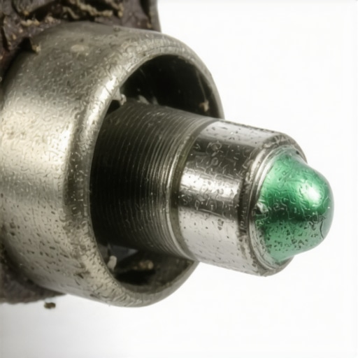
While a burned-out filament is the most frequent cause of hyper-flashing, seasoned technicians know that poor grounding is a more insidious culprit. A ground point serves as the return path for electrical current to the battery; when this path is compromised by rust, paint, or loose bolts, the circuit seeks the path of least resistance. This often leads to ‘backfeeding,’ where the current travels through other lighting filaments to find a ground, resulting in dim operation or erratic blinker speeds. If you are experiencing multiple electrical oddities simultaneously, it is helpful to learn how to find a parasitic battery drain with a 15 multimeter to rule out a more systemic power issue. Investigating the grounding lug near the light housing can often resolve a hyper-flash issue that new bulbs failed to fix.
Can a Simple Signal Fault Trigger a Transmission Error Code?
In the interconnected ecosystem of modern vehicles, electrical noise from a malfunctioning turn signal circuit can occasionally bleed into the Controller Area Network (CAN-bus). While rare, extreme resistance in the lighting loop or a failing multi-function switch can generate electromagnetic interference (EMI) that confuses sensitive modules. This is particularly relevant when the signal circuit shares a wiring harness or grounding bus with transmission sensors. If your gear shifts feel sluggish or erratic during signal usage, you should investigate transmission failures decoded signs and expert fixes to differentiate between a mechanical internal failure and an external electrical ghost. The synchronization of these systems means that a small fault in the ‘low-voltage’ side can sometimes masquerade as a major component failure.
Trace the Voltage Drop Before Buying New Parts
The habit of ‘parts cannon’ diagnostics—throwing new components at a car until the problem disappears—is costly and inefficient. Expert diagnostics require measuring the actual voltage drop across the circuit while it is under load. A multimeter should show near-zero voltage loss on the ground side; any reading above 0.1V suggests high resistance in the wiring itself. This is where the 5 tool for finding electrical shorts in minutes becomes invaluable for the DIY enthusiast. By isolating segments of the harness, you can pinpoint whether the hyper-flashing is caused by a pinched wire behind the bumper or a failing multi-function stalk. According to the National Highway Traffic Safety Administration (NHTSA), proper signaling function is a critical safety requirement, and even minor delays in flash rates can reduce the visibility of your intentions to other drivers on the road.
The Wear and Tear of the Multi-Function Switch
The physical lever on your steering column is more than a plastic handle; it is a complex array of internal copper contacts and springs. Over years of use, these contacts can wear down or become gummed up with old dielectric grease and dust, leading to intermittent signal failure or hyper-flashing despite perfectly healthy bulbs. This is often noticed after other steering-related work has been performed. If you find your signal behavior changed recently, it might be worth asking why your steering wheel is off center after a repair, as steering column adjustments can sometimes disturb aging wiring harnesses. Before you commit to an expensive switch replacement, try using a dedicated electrical contact cleaner to clear away debris from the internal tracks. Have you ever noticed your turn signal changing speed specifically when you hit a bump? Share your weirdest electrical stories in the comments below, or read our guide on deep diagnostics to master your car’s electrical health.
When you actuate the multi-function lever, you are no longer completing a high-voltage circuit in the way older vehicles did. In the modern automotive landscape, that lever sends a low-current logic ‘request’ to the Body Control Module (BCM). The BCM then utilizes internal solid-state drivers to pulse power to the bulbs. This shift from physical switches to digital logic means that hyper-flashing is now a software-generated response to a perceived hardware failure. If the BCM detects a current draw falling outside of the calibrated window—usually between 2 and 5 amps for standard incandescent setups—it instantly modifies the output duty cycle. This digital gatekeeping is why troubleshooting modern vehicles often requires a professional scan tool to view live data streams, allowing you to see exactly what the computer ‘thinks’ is happening at the socket before you start tearing into the dashboard.
How the BCM Rewrites the Rules of Signaling
The logic within the BCM is incredibly sensitive to transient voltage spikes. For instance, if you have recently upgraded your lighting, the computer might perceive the rapid rise-time of an LED as a short circuit. To combat this, some enthusiasts use expert auto repair tips for 2025 to reprogram the BCM’s lighting parameters, essentially ‘teaching’ the car to expect the lower draw of modern diodes. However, if the BCM itself begins to fail due to internal heat or moisture ingress, it can produce a ‘ghost’ hyper-flash where the signals blink rapidly even though every bulb is functional. Accessing these internal fault codes often requires software compliant with the standards set by the Auto Care Association, which advocates for open access to vehicle diagnostic data so that independent shops and DIYers can keep these complex systems running without a trip to the dealership.
Can a poor trailer wiring connection trigger hyper-flashing?
Many drivers overlook the impact of a tow package on the signaling loop. If your vehicle is equipped with a trailer hitch, the wiring harness is often ‘teed’ directly into the rear turn signal lines. A corroded 4-pin connector or a pinched wire on the trailer itself can increase the total resistance of the circuit to the point where the BCM triggers a hyper-flash warning, even if the trailer isn’t currently attached. Moisture trapped inside the trailer plug acts as a bridge, creating a high-resistance ground path that confuses the load-sensing logic. If you suspect your towing setup is the culprit, check out our guide on the 5 tool for finding electrical shorts in minutes to isolate the trailer harness from the main body loom.
Stop Galvanic Corrosion Before It Eats Your Sockets
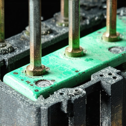
The environment inside a light housing is often more hostile than it appears. Temperature swings lead to condensation, which, when combined with the dissimilar metals found in bulb bases and socket contacts, creates the perfect recipe for galvanic corrosion. This ‘green crust’ is essentially a non-conductive barrier that limits current flow. Even if the bulb looks fine, the resistance at the contact point can be high enough to trigger a hyper-flash. Using a small wire brush and a dab of dielectric grease can prevent this oxidation, ensuring a clean path for the electrons to flow. If you find yourself constantly cleaning sockets, it might be a sign that the housing seals are failing, much like how transmission failures decoded often trace back to simple seal leaks that allow contaminants into a closed system.
The Hidden Link Between Your Blinker and Blind Spot Sensors
In vehicles equipped with Advanced Driver Assistance Systems (ADAS), the turn signal is no longer an isolated circuit; it is a critical input for blind-spot monitoring and lane-change assist features. When you engage the blinker, the CAN-bus network alerts the side-looking radar sensors to increase their polling rate. If the signaling circuit is experiencing hyper-flashing or intermittent connectivity, these safety systems may disable themselves or provide false warnings. This interdependency means that a simple $5 bulb failure can occasionally shut down your most advanced safety features. Have you ever noticed your blind-spot monitor acting up at the same time as your turn signal? This kind of cross-system communication is becoming the norm, and understanding the ‘why’ behind the blink is the first step toward mastering modern car maintenance.
Moving beyond the visible hardware, the underlying architecture of Power Distribution Modules (PDMs) requires a shift in how we approach electrical isolation. In many 21st-century vehicles, the turn signal is no longer a discrete circuit but a virtualized function within the Smart Junction Box (SJB). This module uses Metal-Oxide-Semiconductor Field-Effect Transistors (MOSFETs) to switch power with microsecond precision. Unlike mechanical relays, these solid-state drivers are sensitive to transient voltage sags that occur when other high-draw components—like electric power steering pumps or cooling fans—engage. If the voltage drops too low at the moment of activation, the SJB may interpret the slow rise time as a circuit failure, initiating a latched hyper-flash state that persists until the module is reset via a battery disconnect or professional scan tool.
Stop the Guesswork: Smart Junction Box Logic Defined
When diagnosing these software-driven systems, it is essential to realize that the computer is often looking for very specific ‘signatures’ of current draw. A slight deviation, perhaps caused by using a bulb with a slightly different wattage than the OEM specification, can trigger a diagnostic trouble code (DTC) such as B1315 or B1316. These codes point toward specific open circuits or shorts-to-battery that a standard visual inspection will never catch. To truly master these systems, technicians often leverage expert auto repair tips for 2025 to differentiate between a physical wire break and a software lockout triggered by an ‘implausible’ signal reading from the multi-function switch.
Can Your Blinker Actually Crash Your Vehicle’s Communication Bus?
It sounds like an automotive urban legend, but a shorted turn signal bulb can, in rare instances, introduce electrical noise back into the Controller Area Network (CAN-bus). This occurs when the insulation between the signaling wire and a twisted-pair data wire fails within a shared wiring loom. The result is a cascade of seemingly unrelated errors: your speedometer might drop to zero, or your traction control light might illuminate whenever you signal for a left turn. This phenomenon, known as electromagnetic interference (EMI), highlights why maintaining the integrity of lighting seals is paramount. According to the stringent requirements of the Federal Motor Vehicle Safety Standard (FMVSS) No. 108, turn signal flash rates must remain within a range of 60 to 120 flashes per minute to ensure universal recognition by other motorists, and any deviation can be a sign that your car’s digital nervous system is under attack by stray voltage.
Identify Invisible Resistance with Thermal Imaging
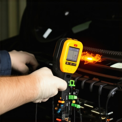
One of the most effective ways to find a hyper-flash culprit that isn’t a bulb is to use a thermal imaging camera. High resistance creates heat long before it creates smoke. By engaging the hazard lights and scanning the fuse box, connectors, and ground lugs, you can literally see the ‘hot spots’ where electricity is struggling to pass through a corroded junction. This method is far faster than traditional back-probing and allows you to catch failures in the early stages of galvanic migration. If you’ve ever wondered why your turn signals behave differently on rainy days, this heat-based diagnostic can reveal the moisture-induced shorts that are invisible to the naked eye.
As we move toward fully autonomous and semi-autonomous driving, the turn signal becomes a primary communication tool for the vehicle’s artificial intelligence. Advanced Driver Assistance Systems (ADAS) rely on the blinker’s status to authorize lane changes or activate side-view cameras. A faulty signaling loop doesn’t just mean a ticket from a police officer; it can mean your car refuses to perform safety maneuvers or provides erratic steering feedback. If your vehicle feels ‘heavy’ or resistant during lane changes, it might be time to investigate transmission failures decoded signs and expert fixes alongside your electrical checks, as the two systems are more intertwined than most drivers realize. If you’re ready to stop the guesswork and master your car’s digital nerves, dive into our expert series on advanced multimeter techniques and share your most challenging electrical ghost stories in the community forum below.
The rapid cadence of a turn signal—technically known as hyper-flashing—is far more than a simple mechanical quirk; it is a deliberate diagnostic feedback mechanism engineered into the vehicle electrical architecture. From an engineering perspective, the turn signal circuit operates as a balanced system where the flasher relay or the Body Control Module (BCM) monitors the specific current draw of the lighting loop. When this balance is disrupted, the system accelerates its cycling frequency to alert the driver of a circuit failure. This intersection of electrical physics and user interface design is a primary example of how the hidden world of vehicle diagnostics provides real-time data to the operator without the need for an external scanner.
The Science of Hyper-Flashing and Why Your Car Is Warning You
In traditional automotive systems, the turn signal flasher is a thermal-mechanical device. It relies on a bi-metallic strip that heats up as current flows through it, eventually bending to break the circuit, cooling down, and resetting. This cycle creates the rhythmic clicking we associate with lane changes. When a bulb burns out, the total resistance of the circuit changes. According to Ohm’s Law, a decrease in resistance leads to an increase in current flow for a given voltage, which in turn causes the thermal strip to heat up much faster than intended. Modern vehicles have replaced these mechanical relays with solid-state logic within the BCM, yet manufacturers purposefully programmed these computers to mimic the rapid-fire behavior of failing thermal relays to ensure drivers recognize the fault immediately. Utilizing top auto repair techniques every car owner should know, one can often diagnose these issues by observing the specific timing of the flash compared to the opposite side of the vehicle.
Why Does the Indicator Speed Up Only When the Engine Is Running?
Many drivers notice that a failing indicator might blink normally while the battery is the sole power source but accelerate once the alternator is engaged. This phenomenon occurs because the alternator raises the system voltage from roughly 12.6V to 14.4V. This slight increase in voltage can be just enough to push a borderline electrical circuit—perhaps one with high resistance due to a corroded socket—into the hyper-flash threshold. If you encounter persistent electrical inconsistencies, it is wise to how to find reliable car service near you in 2025 to ensure your charging system isn’t over-volting your sensitive lighting modules.
Burned Bulbs Change the Circuit’s Resistance
The most common culprit is a simple blown filament in a dual-filament bulb. However, the move toward LED retrofitting has introduced a new layer of complexity to this issue. Because LEDs draw significantly less power than incandescent bulbs, the BCM often perceives the low current draw as a blown bulb, triggering a false hyper-flash. To rectify this, technicians must install load resistors to simulate the draw of a standard bulb. For those looking to optimize their vehicle beyond simple bulb swaps, exploring expert auto repair tips for 2025 can provide insights into modern lighting integration. For detailed safety standards on automotive signaling, professionals often refer to the SAE International (formerly the Society of Automotive Engineers) standards, which dictate the specific frequency ranges required for legal road operation. If your vehicle’s electrical gremlins extend beyond the lighting system, consider investigating whether your transmission performance is being affected by similar grounding issues.
Grounding Failures that Hide in Plain Sight
While a burned-out filament is the most frequent cause of hyper-flashing, seasoned technicians know that poor grounding is a more insidious culprit. A ground point serves as the return path for electrical current to the battery; when this path is compromised by rust, paint, or loose bolts, the circuit seeks the path of least resistance. This often leads to ‘backfeeding,’ where the current travels through other lighting filaments to find a ground, resulting in dim operation or erratic blinker speeds. If you are experiencing multiple electrical oddities simultaneously, it is helpful to learn how to find a parasitic battery drain with a 15 multimeter to rule out a more systemic power issue. Investigating the grounding lug near the light housing can often resolve a hyper-flash issue that new bulbs failed to fix.
Can a Simple Signal Fault Trigger a Transmission Error Code?
In the interconnected ecosystem of modern vehicles, electrical noise from a malfunctioning turn signal circuit can occasionally bleed into the Controller Area Network (CAN-bus). While rare, extreme resistance in the lighting loop or a failing multi-function switch can generate electromagnetic interference (EMI) that confuses sensitive modules. This is particularly relevant when the signal circuit shares a wiring harness or grounding bus with transmission sensors. If your gear shifts feel sluggish or erratic during signal usage, you should investigate transmission failures decoded signs and expert fixes to differentiate between a mechanical internal failure and an external electrical ghost. The synchronization of these systems means that a small fault in the ‘low-voltage’ side can sometimes masquerade as a major component failure.
Trace the Voltage Drop Before Buying New Parts
The habit of ‘parts cannon’ diagnostics—throwing new components at a car until the problem disappears—is costly and inefficient. Expert diagnostics require measuring the actual voltage drop across the circuit while it is under load. A multimeter should show near-zero voltage loss on the ground side; any reading above 0.1V suggests high resistance in the wiring itself. This is where the 5 tool for finding electrical shorts in minutes becomes invaluable for the DIY enthusiast. By isolating segments of the harness, you can pinpoint whether the hyper-flashing is caused by a pinched wire behind the bumper or a failing multi-function stalk. According to the National Highway Traffic Safety Administration (NHTSA), proper signaling function is a critical safety requirement, and even minor delays in flash rates can reduce the visibility of your intentions to other drivers on the road.
The Wear and Tear of the Multi-Function Switch
The physical lever on your steering column is more than a plastic handle; it is a complex array of internal copper contacts and springs. Over years of use, these contacts can wear down or become gummed up with old dielectric grease and dust, leading to intermittent signal failure or hyper-flashing despite perfectly healthy bulbs. This is often noticed after other steering-related work has been performed. If you find your signal behavior changed recently, it might be worth asking why your steering wheel is off center after a repair, as steering column adjustments can sometimes disturb aging wiring harnesses. Before you commit to an expensive switch replacement, try using a dedicated electrical contact cleaner to clear away debris from the internal tracks. Have you ever noticed your turn signal changing speed specifically when you hit a bump? Share your weirdest electrical stories in the comments below, or read our guide on deep diagnostics to master your car’s electrical health.
When you actuate the multi-function lever, you are no longer completing a high-voltage circuit in the way older vehicles did. In the modern automotive landscape, that lever sends a low-current logic ‘request’ to the Body Control Module (BCM). The BCM then utilizes internal solid-state drivers to pulse power to the bulbs. This shift from physical switches to digital logic means that hyper-flashing is now a software-generated response to a perceived hardware failure. If the BCM detects a current draw falling outside of the calibrated window—usually between 2 and 5 amps for standard incandescent setups—it instantly modifies the output duty cycle. This digital gatekeeping is why troubleshooting modern vehicles often requires a professional scan tool to view live data streams, allowing you to see exactly what the computer ‘thinks’ is happening at the socket before you start tearing into the dashboard.
How the BCM Rewrites the Rules of Signaling
The logic within the BCM is incredibly sensitive to transient voltage spikes. For instance, if you have recently upgraded your lighting, the computer might perceive the rapid rise-time of an LED as a short circuit. To combat this, some enthusiasts use expert auto repair tips for 2025 to reprogram the BCM’s lighting parameters, essentially ‘teaching’ the car to expect the lower draw of modern diodes. However, if the BCM itself begins to fail due to internal heat or moisture ingress, it can produce a ‘ghost’ hyper-flash where the signals blink rapidly even though every bulb is functional. Accessing these internal fault codes often requires software compliant with the standards set by the Auto Care Association, which advocates for open access to vehicle diagnostic data so that independent shops and DIYers can keep these complex systems running without a trip to the dealership.
Can a poor trailer wiring connection trigger hyper-flashing?
Many drivers overlook the impact of a tow package on the signaling loop. If your vehicle is equipped with a trailer hitch, the wiring harness is often ‘teed’ directly into the rear turn signal lines. A corroded 4-pin connector or a pinched wire on the trailer itself can increase the total resistance of the circuit to the point where the BCM triggers a hyper-flash warning, even if the trailer isn’t currently attached. Moisture trapped inside the trailer plug acts as a bridge, creating a high-resistance ground path that confuses the load-sensing logic. If you suspect your towing setup is the culprit, check out our guide on the 5 tool for finding electrical shorts in minutes to isolate the trailer harness from the main body loom.
Stop Galvanic Corrosion Before It Eats Your Sockets
The environment inside a light housing is often more hostile than it appears. Temperature swings lead to condensation, which, when combined with the dissimilar metals found in bulb bases and socket contacts, creates the perfect recipe for galvanic corrosion. This ‘green crust’ is essentially a non-conductive barrier that limits current flow. Even if the bulb looks fine, the resistance at the contact point can be high enough to trigger a hyper-flash. Using a small wire brush and a dab of dielectric grease can prevent this oxidation, ensuring a clean path for the electrons to flow. If you find yourself constantly cleaning sockets, it might be a sign that the housing seals are failing, much like how transmission failures decoded often trace back to simple seal leaks that allow contaminants into a closed system.
The Hidden Link Between Your Blinker and Blind Spot Sensors
In vehicles equipped with Advanced Driver Assistance Systems (ADAS), the turn signal is no longer an isolated circuit; it is a critical input for blind-spot monitoring and lane-change assist features. When you engage the blinker, the CAN-bus network alerts the side-looking radar sensors to increase their polling rate. If the signaling circuit is experiencing hyper-flashing or intermittent connectivity, these safety systems may disable themselves or provide false warnings. This interdependency means that a simple $5 bulb failure can occasionally shut down your most advanced safety features. Have you ever noticed your blind-spot monitor acting up at the same time as your turn signal? This kind of cross-system communication is becoming the norm, and understanding the ‘why’ behind the blink is the first step toward mastering modern car maintenance.
Moving beyond the visible hardware, the underlying architecture of Power Distribution Modules (PDMs) requires a shift in how we approach electrical isolation. In many 21st-century vehicles, the turn signal is no longer a discrete circuit but a virtualized function within the Smart Junction Box (SJB). This module uses Metal-Oxide-Semiconductor Field-Effect Transistors (MOSFETs) to switch power with microsecond precision. Unlike mechanical relays, these solid-state drivers are sensitive to transient voltage sags that occur when other high-draw components—like electric power steering pumps or cooling fans—engage. If the voltage drops too low at the moment of activation, the SJB may interpret the slow rise time as a circuit failure, initiating a latched hyper-flash state that persists until the module is reset via a battery disconnect or professional scan tool.
Stop the Guesswork: Smart Junction Box Logic Defined
When diagnosing these software-driven systems, it is essential to realize that the computer is often looking for very specific ‘signatures’ of current draw. A slight deviation, perhaps caused by using a bulb with a slightly different wattage than the OEM specification, can trigger a diagnostic trouble code (DTC) such as B1315 or B1316. These codes point toward specific open circuits or shorts-to-battery that a standard visual inspection will never catch. To truly master these systems, technicians often leverage expert auto repair tips for 2025 to differentiate between a physical wire break and a software lockout triggered by an ‘implausible’ signal reading from the multi-function switch.
Can Your Blinker Actually Crash Your Vehicle’s Communication Bus?
It sounds like an automotive urban legend, but a shorted turn signal bulb can, in rare instances, introduce electrical noise back into the Controller Area Network (CAN-bus). This occurs when the insulation between the signaling wire and a twisted-pair data wire fails within a shared wiring loom. The result is a cascade of seemingly unrelated errors: your speedometer might drop to zero, or your traction control light might illuminate whenever you signal for a left turn. This phenomenon, known as electromagnetic interference (EMI), highlights why maintaining the integrity of lighting seals is paramount. According to the stringent requirements of the Federal Motor Vehicle Safety Standard (FMVSS) No. 108, turn signal flash rates must remain within a range of 60 to 120 flashes per minute to ensure universal recognition by other motorists, and any deviation can be a sign that your car’s digital nervous system is under attack by stray voltage.
Identify Invisible Resistance with Thermal Imaging
One of the most effective ways to find a hyper-flash culprit that isn’t a bulb is to use a thermal imaging camera. High resistance creates heat long before it creates smoke. By engaging the hazard lights and scanning the fuse box, connectors, and ground lugs, you can literally see the ‘hot spots’ where electricity is struggling to pass through a corroded junction. This method is far faster than traditional back-probing and allows you to catch failures in the early stages of galvanic migration. If you’ve ever wondered why your turn signals behave differently on rainy days, this heat-based diagnostic can reveal the moisture-induced shorts that are invisible to the naked eye.
As we move toward fully autonomous and semi-autonomous driving, the turn signal becomes a primary communication tool for the vehicle’s artificial intelligence. Advanced Driver Assistance Systems (ADAS) rely on the blinker’s status to authorize lane changes or activate side-view cameras. A faulty signaling loop doesn’t just mean a ticket from a police officer; it can mean your car refuses to perform safety maneuvers or provides erratic steering feedback. If your vehicle feels ‘heavy’ or resistant during lane changes, it might be time to investigate transmission failures decoded signs and expert fixes alongside your electrical checks, as the two systems are more intertwined than most drivers realize. If you’re ready to stop the guesswork and master your car’s digital nerves, dive into our expert series on advanced multimeter techniques and share your most challenging electrical ghost stories in the community forum below.
Expert Insights & Advanced Considerations
Voltage Drop Testing Beats Simple Continuity Checks
Checking for continuity is a rookie mistake in signaling diagnostics because a single strand of copper can show continuity while failing to carry the amperage required for an incandescent bulb. Expert technicians use a voltage drop test under load to find resistance that a simple ohm meter misses. By utilizing the 5 tool for finding electrical shorts in minutes, you can see exactly where the voltage disappears before it reaches the socket.
The Smart Junction Box Changes the Diagnostic Playbook
Unlike old relays that would either work or click, a Smart Junction Box (SJB) can ‘latch’ a fault. If the SJB detects a short circuit, it may permanently disable the output to that bulb to protect its internal MOSFET drivers. This means even if you fix the wiring, the hyper-flashing might persist until you perform a hard module reset or clear the B-series DTCs with a professional-grade scanner.
Your Blinker Status Dictates ADAS Behavior
Modern safety suites use the turn signal as a trigger for high-level logic. If the signaling circuit fails, the vehicle often defaults to a limited-functionality mode for features like lane-keep assist. This interdependency makes the humble blinker a critical safety component, emphasizing why expert auto repair tips for 2025 focus heavily on the integration of lighting and data networks.
Curated Expert Resources
SAE International J588 Standard: This is the definitive engineering document for turn signal performance. It provides the technical basis for why your car is programmed to hyper-flash when current draw falls outside specific millivolt thresholds.
NHTSA FMVSS No. 108: The Federal Motor Vehicle Safety Standards for lighting. Understanding this resource is essential for anyone retrofitting LED bulbs, as it outlines the legal frequency requirements that your vehicle’s BCM is trying to maintain.
Auto Care Association – Right to Repair: A vital resource for enthusiasts looking for open-source diagnostic data. They provide advocacy and documentation that help DIYers bypass dealership lockouts when resetting complex lighting control modules.
Final Expert Perspective
Hyper-flashing is not just an annoyance; it is your car’s most direct way of communicating a complex electrical imbalance. Whether it is a simple blown filament or a sophisticated software lockout within the BCM, the rapid blink is a call to action for a deeper diagnostic approach. By looking past the bulb and investigating grounding points, voltage drops, and bus interference, you ensure your vehicle remains both visible and safe. If you have mastered your own lighting circuits, we invite you to explore more technical deep-dives on the hidden world of vehicle diagnostics or share your most complex electrical troubleshooting wins with our community of specialists.