Empirical Diagnostics Beyond Diagnostic Trouble Codes
In modern powertrain management, closed-loop fuel feedback systems rely heavily on wideband and narrowband oxygen sensors (O2 sensors) to maintain stoichiometric air-fuel ratios (~14.7:1 for gasoline engines). While onboard diagnostic (OBD-II) protocols trigger malfunction indicator lights when signal parameters exceed pre-set thresholds, waiting for a check engine light often leaves underlying combustion inefficiencies unresolved. Advanced vehicle diagnostics require technicians and experienced car owners to evaluate primary engine symptoms, chemical output indicators, and dynamic feedback responses before relying entirely on automated scans.
When an oxygen sensor deteriorates due to siloxane poisoning, oil ash deposits, or internal thermal degradation, its voltage output slows down or drops out entirely. Rather than relying on a digital scanner, experienced automotive specialists inspect live engine metrics using physical symptoms and multi-meter testing. Recognizing these early warning signs is critical to preventing long-term damage to the catalytic converter and maintaining peak fuel efficiency.
If you encounter complex engine performance issues alongside shifting problems, review our breakdown on transmission failures decoded: signs and expert fixes to isolate powertrain malfunctions efficiently.
Physical and Chemical Indicators of Oxygen Sensor Degradation
A decaying oxygen sensor directly alters the engine control unit’s (ECU) short-term fuel trim calculations. When a sensor fails lean, it reports excess oxygen content to the ECU, triggering an aggressive, unnecessary enrichment strategy. This over-fueling leads to distinct physical symptoms:
- Sulfur and Unburned Hydrocarbon Odors: A persistent rotten egg smell indicates that excess fuel is saturating the catalytic converter, causing extreme thermal stress on the precious metal substrates. Learn more about evaluating unusual exhaust odors in our guide on why your car smells like rotten eggs after a long drive.
- Severe Idle Hesitation and Stalling: Incorrect air-fuel mixture adjustments disrupt idle stability, resulting in hunting RPMs or misfires during engine warm-up phases.
- Sooty Spark Plug Fouling: Removing a spark plug reveals heavy, velvety black carbon deposits resulting from prolonged rich combustion.
According to technical research published by the Society of Automotive Engineers (SAE), dynamic response degradation in exhaust sensors often occurs long before severe circuit failure thresholds are recognized by basic engine control strategies.
Why Is Your Engine Hesitating at Stoplights Even Without a Light on the Dash?
Hesitation under light load—particularly during deceleration or idle transitions—occurs when an O2 sensor’s internal response time degrades from milliseconds to seconds. This delayed feedback loop causes the ECU to momentarily trim fuel improperly during load changes. If your vehicle exhibits fluctuating performance at idle, read our technical breakdown on why your engine hesitates at stoplights to pinpoint the root cause.
Evaluating Sensor Output via Digital Multimeter Test
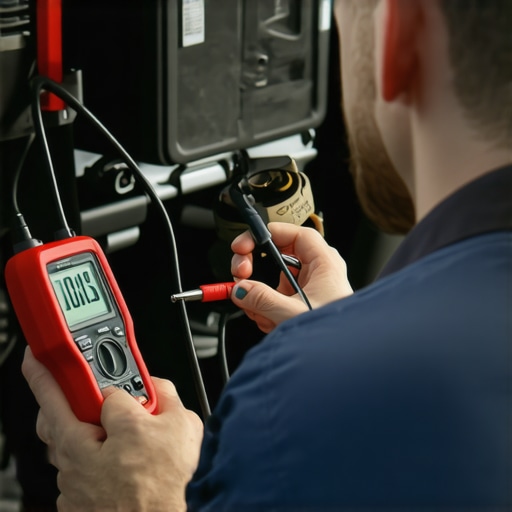
To definitively test an O2 sensor without an OBD reader, back-probe the sensor signal wire using a high-impedance digital multimeter (DMM) set to DC millivolts. Connect the negative probe to a solid chassis ground and start the engine, allowing it to reach normal operating temperature (~180°F to 200°F) so the ECU transitions into closed-loop mode.
A healthy narrowband sensor should rapidly toggle between 0.1V (lean) and 0.9V (rich) roughly 1 to 2 times per second at 2,000 RPM. If the voltage stays pinned below 0.4V or fluctuates lethargically, the sensor is contaminated or structurally exhausted. Mastering these manual testing protocols forms the core of effective vehicle diagnostics and professional auto repair techniques.
Need help troubleshooting complex drivability, electrical, or drivetrain issues? Contact our expert car service team today to consult with certified master technicians.
Exposing Hidden Air Leaks That Fool Your ECU
Unmetered air entering the engine downstream of the mass air flow (MAF) sensor presents one of the most frustrating obstacles when diagnosing fuel trim anomalies. When a vacuum leak occurs around an intake manifold gasket or a brittle vacuum hose, the extra oxygen flows directly past the combustion chamber into the exhaust manifold. The downstream or upstream oxygen sensor senses this excess oxygen and correctly reports a lean condition. However, because the leak originates outside normal metering pathways, the ECU mistakenly assumes the engine is under-fueled, pumping in excess gas that washes cylinder walls and fouls spark plugs.
Instead of immediately replacing an O2 sensor that appears stuck on a lean reading, technicians use propane enrichment or smoke testing to verify intake integrity. Artificially introducing a small stream of unlit propane near suspected leak zones while monitoring live sensor voltage will instantly cause a functional O2 sensor to spike toward 0.9V. If the voltage jumps immediately, the sensor is operating properly and reacting to real atmospheric air leaks rather than an internal electrical fault.
Could a Lazy Heater Circuit Be Ruining Your Cold-Start Fuel Economy?
Modern planar and thimble O2 sensors utilize an internal ceramic heating element to reach their mandatory operational temperature of approximately 600°F (315°C) within seconds of a cold start. When this heater element breaks down due to vibration or age, the sensor relies entirely on thermal energy from exhaust gases to stay active. Consequently, during extended idling or stop-and-go traffic, the sensor cools down, drops out of closed-loop operation, and defaults to a rich emergency fuel map. If you experience unexpected morning starting issues or erratic idle behavior, exploring the $12 fix for a car that is hard to start in the morning can help you isolate simple ignition and fuel delivery glitches from sensor failure.
Distinguishing Between Contamination and Electrical Wear
Visual inspection of a removed oxygen sensor often reveals the exact environmental factor that caused its failure, offering clear proof of deeper mechanical issues within the engine block:
- Silicone Poisoning: A powdery white coating indicates silicone contamination, usually stemming from improper use of RTV gasket sealant or internal coolant consumption. If you suspect coolant is entering the combustion chamber, check our guide on why your oil looks like a milkshake to catch head gasket failure early.
- Oil Ash Accumulation: Heavy, crusty grey deposits point directly to worn valve guide seals or stuck oil control rings allowing engine oil into the combustion chamber. Understanding how to manage oil consumption is covered in depth in our analysis on the secret to stopping engine oil consumption.
- Soot and Carbon Clogging: Thick, oily black deposits signal persistent rich operation, often tied to leaky fuel injectors, excessive fuel pressure, or a stuck-open thermostat. Learn how to test your cooling system properly by reading how to verify your thermostat is actually opening.
Extensive field data compiled by the National Institute for Automotive Service Excellence (ASE) highlights that over 40% of early sensor replacements stem from preventable fluid contamination rather than natural electrical degradation.
Isolating Ground Loops and Harness Degradation
In high-mileage vehicles, persistent signal distortion often originates in the engine wiring harness rather than the sensor housing itself. Corroded ground straps create resistance, lifting the reference ground above zero volts and causing the ECU to misinterpret valid signal swings. Back-probing the sensor’s dedicated ground wire with a multimeter should yield less than 0.05 volts DC relative to the negative battery terminal. If voltage drop is present across the ground wire, clean or supplement your engine grounds to restore precise sensor readings instantly.
Have you successfully diagnosed a stubborn fuel trim problem using multimeter testing on your own driveway? Drop a comment below with your diagnostic setup or share this guide with fellow car enthusiasts who love fixing vehicles the right way!
Translating Short-Term and Long-Term Fuel Trims into Actionable Repair Plans
Understanding live engine data streams requires looking beyond snapshot fault codes and examining how the ECU dynamically reacts to real-time combustion parameters. Fuel trims represent the percentage shift in fuel delivery necessary to maintain a theoretical stoichiometric ratio. Short-term fuel trim (STFT) responds instantaneously to rapid throttle movements and transient sensor changes, while long-term fuel trim (LTFT) serves as a learned baseline memory, compensating for long-term mechanical wear, subtle vacuum leaks, or gradual injector clogging.
When analyzing a vehicle with drivability complaints, monitoring the mathematical sum of STFT and LTFT at different engine speeds provides clear diagnostic direction. For example, if combined fuel trims show +22% at idle but drop down to a normal +3% at 2,500 RPM, you are almost certainly dealing with a vacuum leak downstream of the throttle body. At higher engine speeds, the total volume of intake air increases significantly, rendering the fixed volume of unmetered vacuum leak negligible. Conversely, if total fuel trims remain excessively positive across all RPM ranges, the issue shifts toward restricted fuel delivery, such as a clogged fuel filter, a weak fuel pump, or contaminated injectors.
Why Do Fuel Trims Spike Positive Only During Engine Deceleration?
When fuel trims jump significantly positive during coast-down or deceleration, the engine control unit is detecting unexpected lean spikes right when the fuel injectors should be cutting back flow. This phenomenon frequently points to an internal leak within the positive crankcase ventilation (PCV) valve system or a torn brake booster diaphragm. As engine vacuum peaks during deceleration, high manifold vacuum draws unmetered air directly through compromised internal seals, pulling lean air into the intake manifold and forcing the ECU to overcompensate by adding fuel.
Simulating Sensor Signals to Verify ECU Integrity
Before condemning an engine controller or replacing expensive harness runs, experienced technicians perform signal simulation directly at the sensor connector to verify ECU processing accuracy. If an O2 sensor signal appears stuck at 0.1V and the ECU continuously adds fuel, you must determine whether the ECU’s internal analog-to-digital converter is actually reading the pin correctly or if the signal line is shorted to ground.
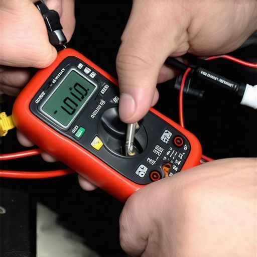
By using a dedicated signal generator or introducing a controlled voltage through a high-impedance resistor, you can safely inject a false 0.9V rich signal into the ECU signal harness. If the ECU live data stream immediately reflects the 0.9V input and responds by dropping short-term fuel trim into negative percentages, you have proven that the ECU, harness wiring, and processing hardware are fully functional. This pinpoints the fault exclusively to the sensor itself or an actual physical air-fuel ratio imbalance in the exhaust stream. For comprehensive guidance on automotive electrical standards and signal validation, refer to technical documentation provided by the International Organization for Standardization (ISO).
Advanced Scope Analysis of Wideband Air-Fuel Ratio Sensors
Unlike traditional narrowband oxygen sensors that simply toggle back and forth around 0.45 volts, modern wideband air-fuel (A/F) ratio sensors utilize a dual-cell structure—a Nernst concentration cell combined with an internal oxygen pumping cell. The engine control unit continuously adjusts the current flowing through the pumping cell to keep the Nernst cell voltage locked at a stable reference point (typically 450 mV). The amount and direction of current required to maintain this balance directly translates into an exact air-fuel ratio, allowing the ECU to measure mixtures as rich as 10:1 or as lean as free air.
Diagnosing a wideband sensor requires evaluating current flow in milliamps rather than simple voltage drops. Using a digital storage oscilloscope (DSO) equipped with a sensitive current probe, technicians can capture microsecond delays in pumping current response during rapid snap-throttle tests. A slow current response directly signals internal sensor poisoning or ceramic substrate degradation, long before standard OBD-II monitors flag an active trouble code.
How Can You Confirm Wideband Current Drift Without Diagnostic Software?
Measuring current drift on wideband circuits manually requires back-probing the pump current line (Ip+) with a precision oscilloscope capable of reading low-milliamperage signals. By rapidly cycling the throttle from idle to wide-open conditions, the scope trace must instantly jump from zero milliamps into negative current territory (rich transition) and snap back up to positive current (lean transition) as throttle snaps shut. Any rounding or lazy slope on the wave crest confirms that the internal diffusion layer is restricted by exhaust soot or thermal breakdown.
Evaluating Exhaust Backpressure and Catalytic Converter Efficiency
Downstream oxygen sensors serve a primary function: monitoring the oxygen storage capacity (OSC) of the catalytic converter. While upstream sensors continuously fluctuate to maintain optimal combustion, a healthy catalytic converter stores surplus oxygen during lean cycles and uses it to oxidize unburned hydrocarbons and carbon monoxide during rich cycles. Consequently, a properly functioning downstream sensor should display a virtually flat, steady voltage line between 0.6V and 0.8V during steady cruising conditions.
If the downstream sensor begins mirroring the rapid oscillating waveform of the upstream sensor, the catalytic converter has lost its chemical storage capacity. However, before replacing an expensive catalyst, technicians must rule out upstream exhaust leaks. Even tiny cracks in the exhaust manifold or a deteriorating flex pipe gasket will draw outside air into the exhaust stream via Venturi effect pulses, fooling both upstream and downstream sensors into registering incorrect oxygen levels.
Empirical Diagnostics Beyond Diagnostic Trouble Codes
In modern powertrain management, closed-loop fuel feedback systems rely heavily on wideband and narrowband oxygen sensors (O2 sensors) to maintain stoichiometric air-fuel ratios (~14.7:1 for gasoline engines). While onboard diagnostic (OBD-II) protocols trigger malfunction indicator lights when signal parameters exceed pre-set thresholds, waiting for a check engine light often leaves underlying combustion inefficiencies unresolved. Advanced vehicle diagnostics require technicians and experienced car owners to evaluate primary engine symptoms, chemical output indicators, and dynamic feedback responses before relying entirely on automated scans.
When an oxygen sensor deteriorates due to siloxane poisoning, oil ash deposits, or internal thermal degradation, its voltage output slows down or drops out entirely. Rather than relying on a digital scanner, experienced automotive specialists inspect live engine metrics using physical symptoms and multi-meter testing. Recognizing these early warning signs is critical to preventing long-term damage to the catalytic converter and maintaining peak fuel efficiency.
If you encounter complex engine performance issues alongside shifting problems, review our breakdown on transmission failures decoded: signs and expert fixes to isolate powertrain malfunctions efficiently.
Physical and Chemical Indicators of Oxygen Sensor Degradation
A decaying oxygen sensor directly alters the engine control unit’s (ECU) short-term fuel trim calculations. When a sensor fails lean, it reports excess oxygen content to the ECU, triggering an aggressive, unnecessary enrichment strategy. This over-fueling leads to distinct physical symptoms:
- Sulfur and Unburned Hydrocarbon Odors: A persistent rotten egg smell indicates that excess fuel is saturating the catalytic converter, causing extreme thermal stress on the precious metal substrates. Learn more about evaluating unusual exhaust odors in our guide on why your car smells like rotten eggs after a long drive.
- Severe Idle Hesitation and Stalling: Incorrect air-fuel mixture adjustments disrupt idle stability, resulting in hunting RPMs or misfires during engine warm-up phases.
- Sooty Spark Plug Fouling: Removing a spark plug reveals heavy, velvety black carbon deposits resulting from prolonged rich combustion.
According to technical research published by the Society of Automotive Engineers (SAE), dynamic response degradation in exhaust sensors often occurs long before severe circuit failure thresholds are recognized by basic engine control strategies.
Why Is Your Engine Hesitating at Stoplights Even Without a Light on the Dash?
Hesitation under light load—particularly during deceleration or idle transitions—occurs when an O2 sensor’s internal response time degrades from milliseconds to seconds. This delayed feedback loop causes the ECU to momentarily trim fuel improperly during load changes. If your vehicle exhibits fluctuating performance at idle, read our technical breakdown on why your engine hesitates at stoplights to pinpoint the root cause.
Evaluating Sensor Output via Digital Multimeter Test
To definitively test an O2 sensor without an OBD reader, back-probe the sensor signal wire using a high-impedance digital multimeter (DMM) set to DC millivolts. Connect the negative probe to a solid chassis ground and start the engine, allowing it to reach normal operating temperature (~180°F to 200°F) so the ECU transitions into closed-loop mode.
A healthy narrowband sensor should rapidly toggle between 0.1V (lean) and 0.9V (rich) roughly 1 to 2 times per second at 2,000 RPM. If the voltage stays pinned below 0.4V or fluctuates lethargically, the sensor is contaminated or structurally exhausted. Mastering these manual testing protocols forms the core of effective vehicle diagnostics and professional auto repair techniques.
Need help troubleshooting complex drivability, electrical, or drivetrain issues? Contact our expert car service team today to consult with certified master technicians.
Exposing Hidden Air Leaks That Fool Your ECU
Unmetered air entering the engine downstream of the mass air flow (MAF) sensor presents one of the most frustrating obstacles when diagnosing fuel trim anomalies. When a vacuum leak occurs around an intake manifold gasket or a brittle vacuum hose, the extra oxygen flows directly past the combustion chamber into the exhaust manifold. The downstream or upstream oxygen sensor senses this excess oxygen and correctly reports a lean condition. However, because the leak originates outside normal metering pathways, the ECU mistakenly assumes the engine is under-fueled, pumping in excess gas that washes cylinder walls and fouls spark plugs.
Instead of immediately replacing an O2 sensor that appears stuck on a lean reading, technicians use propane enrichment or smoke testing to verify intake integrity. Artificially introducing a small stream of unlit propane near suspected leak zones while monitoring live sensor voltage will instantly cause a functional O2 sensor to spike toward 0.9V. If the voltage jumps immediately, the sensor is operating properly and reacting to real atmospheric air leaks rather than an internal electrical fault.
Could a Lazy Heater Circuit Be Ruining Your Cold-Start Fuel Economy?
Modern planar and thimble O2 sensors utilize an internal ceramic heating element to reach their mandatory operational temperature of approximately 600°F (315°C) within seconds of a cold start. When this heater element breaks down due to vibration or age, the sensor relies entirely on thermal energy from exhaust gases to stay active. Consequently, during extended idling or stop-and-go traffic, the sensor cools down, drops out of closed-loop operation, and defaults to a rich emergency fuel map. If you experience unexpected morning starting issues or erratic idle behavior, exploring the $12 fix for a car that is hard to start in the morning can help you isolate simple ignition and fuel delivery glitches from sensor failure.
Distinguishing Between Contamination and Electrical Wear
Visual inspection of a removed oxygen sensor often reveals the exact environmental factor that caused its failure, offering clear proof of deeper mechanical issues within the engine block:
- Silicone Poisoning: A powdery white coating indicates silicone contamination, usually stemming from improper use of RTV gasket sealant or internal coolant consumption. If you suspect coolant is entering the combustion chamber, check our guide on why your oil looks like a milkshake to catch head gasket failure early.
- Oil Ash Accumulation: Heavy, crusty grey deposits point directly to worn valve guide seals or stuck oil control rings allowing engine oil into the combustion chamber. Understanding how to manage oil consumption is covered in depth in our analysis on the secret to stopping engine oil consumption.
- Soot and Carbon Clogging: Thick, oily black deposits signal persistent rich operation, often tied to leaky fuel injectors, excessive fuel pressure, or a stuck-open thermostat. Learn how to test your cooling system properly by reading how to verify your thermostat is actually opening.
Extensive field data compiled by the National Institute for Automotive Service Excellence (ASE) highlights that over 40% of early sensor replacements stem from preventable fluid contamination rather than natural electrical degradation.
Isolating Ground Loops and Harness Degradation
In high-mileage vehicles, persistent signal distortion often originates in the engine wiring harness rather than the sensor housing itself. Corroded ground straps create resistance, lifting the reference ground above zero volts and causing the ECU to misinterpret valid signal swings. Back-probing the sensor’s dedicated ground wire with a multimeter should yield less than 0.05 volts DC relative to the negative battery terminal. If voltage drop is present across the ground wire, clean or supplement your engine grounds to restore precise sensor readings instantly.
Have you successfully diagnosed a stubborn fuel trim problem using multimeter testing on your own driveway? Drop a comment below with your diagnostic setup or share this guide with fellow car enthusiasts who love fixing vehicles the right way!
Translating Short-Term and Long-Term Fuel Trims into Actionable Repair Plans
Understanding live engine data streams requires looking beyond snapshot fault codes and examining how the ECU dynamically reacts to real-time combustion parameters. Fuel trims represent the percentage shift in fuel delivery necessary to maintain a theoretical stoichiometric ratio. Short-term fuel trim (STFT) responds instantaneously to rapid throttle movements and transient sensor changes, while long-term fuel trim (LTFT) serves as a learned baseline memory, compensating for long-term mechanical wear, subtle vacuum leaks, or gradual injector clogging.
When analyzing a vehicle with drivability complaints, monitoring the mathematical sum of STFT and LTFT at different engine speeds provides clear diagnostic direction. For example, if combined fuel trims show +22% at idle but drop down to a normal +3% at 2,500 RPM, you are almost certainly dealing with a vacuum leak downstream of the throttle body. At higher engine speeds, the total volume of intake air increases significantly, rendering the fixed volume of unmetered vacuum leak negligible. Conversely, if total fuel trims remain excessively positive across all RPM ranges, the issue shifts toward restricted fuel delivery, such as a clogged fuel filter, a weak fuel pump, or contaminated injectors.
Why Do Fuel Trims Spike Positive Only During Engine Deceleration?
When fuel trims jump significantly positive during coast-down or deceleration, the engine control unit is detecting unexpected lean spikes right when the fuel injectors should be cutting back flow. This phenomenon frequently points to an internal leak within the positive crankcase ventilation (PCV) valve system or a torn brake booster diaphragm. As engine vacuum peaks during deceleration, high manifold vacuum draws unmetered air directly through compromised internal seals, pulling lean air into the intake manifold and forcing the ECU to overcompensate by adding fuel.
Simulating Sensor Signals to Verify ECU Integrity
Before condemning an engine controller or replacing expensive harness runs, experienced technicians perform signal simulation directly at the sensor connector to verify ECU processing accuracy. If an O2 sensor signal appears stuck at 0.1V and the ECU continuously adds fuel, you must determine whether the ECU’s internal analog-to-digital converter is actually reading the pin correctly or if the signal line is shorted to ground.
By using a dedicated signal generator or introducing a controlled voltage through a high-impedance resistor, you can safely inject a false 0.9V rich signal into the ECU signal harness. If the ECU live data stream immediately reflects the 0.9V input and responds by dropping short-term fuel trim into negative percentages, you have proven that the ECU, harness wiring, and processing hardware are fully functional. This pinpoints the fault exclusively to the sensor itself or an actual physical air-fuel ratio imbalance in the exhaust stream. For comprehensive guidance on automotive electrical standards and signal validation, refer to technical documentation provided by the International Organization for Standardization (ISO).
Advanced Scope Analysis of Wideband Air-Fuel Ratio Sensors
Unlike traditional narrowband oxygen sensors that simply toggle back and forth around 0.45 volts, modern wideband air-fuel (A/F) ratio sensors utilize a dual-cell structure—a Nernst concentration cell combined with an internal oxygen pumping cell. The engine control unit continuously adjusts the current flowing through the pumping cell to keep the Nernst cell voltage locked at a stable reference point (typically 450 mV). The amount and direction of current required to maintain this balance directly translates into an exact air-fuel ratio, allowing the ECU to measure mixtures as rich as 10:1 or as lean as free air.
Diagnosing a wideband sensor requires evaluating current flow in milliamps rather than simple voltage drops. Using a digital storage oscilloscope (DSO) equipped with a sensitive current probe, technicians can capture microsecond delays in pumping current response during rapid snap-throttle tests. A slow current response directly signals internal sensor poisoning or ceramic substrate degradation, long before standard OBD-II monitors flag an active trouble code.
How Can You Confirm Wideband Current Drift Without Diagnostic Software?
Measuring current drift on wideband circuits manually requires back-probing the pump current line (Ip+) with a precision oscilloscope capable of reading low-milliamperage signals. By rapidly cycling the throttle from idle to wide-open conditions, the scope trace must instantly jump from zero milliamps into negative current territory (rich transition) and snap back up to positive current (lean transition) as throttle snaps shut. Any rounding or lazy slope on the wave crest confirms that the internal diffusion layer is restricted by exhaust soot or thermal breakdown.
Evaluating Exhaust Backpressure and Catalytic Converter Efficiency
Downstream oxygen sensors serve a primary function: monitoring the oxygen storage capacity (OSC) of the catalytic converter. While upstream sensors continuously fluctuate to maintain optimal combustion, a healthy catalytic converter stores surplus oxygen during lean cycles and uses it to oxidize unburned hydrocarbons and carbon monoxide during rich cycles. Consequently, a properly functioning downstream sensor should display a virtually flat, steady voltage line between 0.6V and 0.8V during steady cruising conditions.
If the downstream sensor begins mirroring the rapid oscillating waveform of the upstream sensor, the catalytic converter has lost its chemical storage capacity. However, before replacing an expensive catalyst, technicians must rule out upstream exhaust leaks. Even tiny cracks in the exhaust manifold or a deteriorating flex pipe gasket will draw outside air into the exhaust stream via Venturi effect pulses, fooling both upstream and downstream sensors into registering incorrect oxygen levels.
Spot Exhaust Restriction Before Destroying Your Catalyst
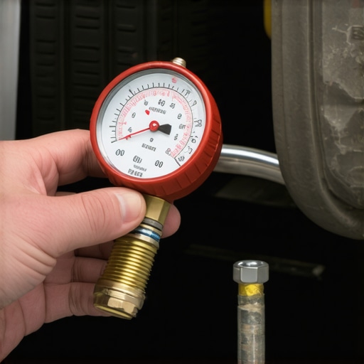
When internal monolith structures break down inside a converter, physical obstruction increases exhaust backpressure exponentially. This restriction impedes fresh intake air charge, chokes power output at higher engine loads, and forces toxic thermal buildup straight into the cylinder head. Measuring manifold absolute pressure (MAP) or using a dedicated backpressure gauge inserted into the upstream sensor port instantly exposes a physical flow restriction. Under full load or 2,500 RPM free-revving, backpressure on a healthy system must remain below 1.25 PSI (0.08 bar). Exceeding 2.0 PSI indicates severe structural melting or soot clogging that requires immediate component renewal.
Can a Blown Intake Gasket Trick Modern Wideband Sensors?
Intake gasket leaks occurring near a single cylinder frequently create localized lean conditions that bypass overall MAF tracking. The resulting misfire pushes raw oxygen straight past the exhaust valves into the manifold. Wideband sensors read this raw oxygen surge and command an engine-wide fuel enrichment, flooding the remaining healthy cylinders. Analyzing cylinder-specific misfire counters alongside real-time wideband pump current prevents misdiagnosing a simple mechanical seal failure as a complex electronic fault. For technical guidelines regarding gasket replacement standards and intake manifold torque specs, inspect technical service bulletins managed by the European Organisation for Technical Assessment (EOTA).
Put Advanced Diagnostic Strategies to Work
Interpreting live engine data and evaluating dynamic sensor signals allows automotive technicians to resolve complex drivability faults quickly and accurately. Relying solely on diagnostic trouble codes often leads to unnecessary parts replacement and missed mechanical flaws. By systematically measuring voltage drop, testing pump current response, and verifying physical intake integrity, you eliminate costly diagnostic guessing games permanently. If you are dealing with persistent fuel trim errors, severe driveability issues, or unexplainable performance glitches on your vehicle, schedule a diagnostic consultation with our master technicians today to restore factory efficiency!
Empirical Diagnostics Beyond Diagnostic Trouble Codes
In modern powertrain management, closed-loop fuel feedback systems rely heavily on wideband and narrowband oxygen sensors (O2 sensors) to maintain stoichiometric air-fuel ratios (~14.7:1 for gasoline engines). While onboard diagnostic (OBD-II) protocols trigger malfunction indicator lights when signal parameters exceed pre-set thresholds, waiting for a check engine light often leaves underlying combustion inefficiencies unresolved. Advanced vehicle diagnostics require technicians and experienced car owners to evaluate primary engine symptoms, chemical output indicators, and dynamic feedback responses before relying entirely on automated scans.
When an oxygen sensor deteriorates due to siloxane poisoning, oil ash deposits, or internal thermal degradation, its voltage output slows down or drops out entirely. Rather than relying on a digital scanner, experienced automotive specialists inspect live engine metrics using physical symptoms and multi-meter testing. Recognizing these early warning signs is critical to preventing long-term damage to the catalytic converter and maintaining peak fuel efficiency.
If you encounter complex engine performance issues alongside shifting problems, review our breakdown on transmission failures decoded: signs and expert fixes to isolate powertrain malfunctions efficiently.
Physical and Chemical Indicators of Oxygen Sensor Degradation
A decaying oxygen sensor directly alters the engine control unit’s (ECU) short-term fuel trim calculations. When a sensor fails lean, it reports excess oxygen content to the ECU, triggering an aggressive, unnecessary enrichment strategy. This over-fueling leads to distinct physical symptoms:
- Sulfur and Unburned Hydrocarbon Odors: A persistent rotten egg smell indicates that excess fuel is saturating the catalytic converter, causing extreme thermal stress on the precious metal substrates. Learn more about evaluating unusual exhaust odors in our guide on why your car smells like rotten eggs after a long drive.
- Severe Idle Hesitation and Stalling: Incorrect air-fuel mixture adjustments disrupt idle stability, resulting in hunting RPMs or misfires during engine warm-up phases.
- Sooty Spark Plug Fouling: Removing a spark plug reveals heavy, velvety black carbon deposits resulting from prolonged rich combustion.
According to technical research published by the Society of Automotive Engineers (SAE), dynamic response degradation in exhaust sensors often occurs long before severe circuit failure thresholds are recognized by basic engine control strategies.
Why Is Your Engine Hesitating at Stoplights Even Without a Light on the Dash?
Hesitation under light load—particularly during deceleration or idle transitions—occurs when an O2 sensor’s internal response time degrades from milliseconds to seconds. This delayed feedback loop causes the ECU to momentarily trim fuel improperly during load changes. If your vehicle exhibits fluctuating performance at idle, read our technical breakdown on why your engine hesitates at stoplights to pinpoint the root cause.
Evaluating Sensor Output via Digital Multimeter Test
To definitively test an O2 sensor without an OBD reader, back-probe the sensor signal wire using a high-impedance digital multimeter (DMM) set to DC millivolts. Connect the negative probe to a solid chassis ground and start the engine, allowing it to reach normal operating temperature (~180°F to 200°F) so the ECU transitions into closed-loop mode.
A healthy narrowband sensor should rapidly toggle between 0.1V (lean) and 0.9V (rich) roughly 1 to 2 times per second at 2,000 RPM. If the voltage stays pinned below 0.4V or fluctuates lethargically, the sensor is contaminated or structurally exhausted. Mastering these manual testing protocols forms the core of effective vehicle diagnostics and professional auto repair techniques.
Need help troubleshooting complex drivability, electrical, or drivetrain issues? Contact our expert car service team today to consult with certified master technicians.
Exposing Hidden Air Leaks That Fool Your ECU
Unmetered air entering the engine downstream of the mass air flow (MAF) sensor presents one of the most frustrating obstacles when diagnosing fuel trim anomalies. When a vacuum leak occurs around an intake manifold gasket or a brittle vacuum hose, the extra oxygen flows directly past the combustion chamber into the exhaust manifold. The downstream or upstream oxygen sensor senses this excess oxygen and correctly reports a lean condition. However, because the leak originates outside normal metering pathways, the ECU mistakenly assumes the engine is under-fueled, pumping in excess gas that washes cylinder walls and fouls spark plugs.
Instead of immediately replacing an O2 sensor that appears stuck on a lean reading, technicians use propane enrichment or smoke testing to verify intake integrity. Artificially introducing a small stream of unlit propane near suspected leak zones while monitoring live sensor voltage will instantly cause a functional O2 sensor to spike toward 0.9V. If the voltage jumps immediately, the sensor is operating properly and reacting to real atmospheric air leaks rather than an internal electrical fault.
Could a Lazy Heater Circuit Be Ruining Your Cold-Start Fuel Economy?
Modern planar and thimble O2 sensors utilize an internal ceramic heating element to reach their mandatory operational temperature of approximately 600°F (315°C) within seconds of a cold start. When this heater element breaks down due to vibration or age, the sensor relies entirely on thermal energy from exhaust gases to stay active. Consequently, during extended idling or stop-and-go traffic, the sensor cools down, drops out of closed-loop operation, and defaults to a rich emergency fuel map. If you experience unexpected morning starting issues or erratic idle behavior, exploring the $12 fix for a car that is hard to start in the morning can help you isolate simple ignition and fuel delivery glitches from sensor failure.
Distinguishing Between Contamination and Electrical Wear
Visual inspection of a removed oxygen sensor often reveals the exact environmental factor that caused its failure, offering clear proof of deeper mechanical issues within the engine block:
- Silicone Poisoning: A powdery white coating indicates silicone contamination, usually stemming from improper use of RTV gasket sealant or internal coolant consumption. If you suspect coolant is entering the combustion chamber, check our guide on why your oil looks like a milkshake to catch head gasket failure early.
- Oil Ash Accumulation: Heavy, crusty grey deposits point directly to worn valve guide seals or stuck oil control rings allowing engine oil into the combustion chamber. Understanding how to manage oil consumption is covered in depth in our analysis on the secret to stopping engine oil consumption.
- Soot and Carbon Clogging: Thick, oily black deposits signal persistent rich operation, often tied to leaky fuel injectors, excessive fuel pressure, or a stuck-open thermostat. Learn how to test your cooling system properly by reading how to verify your thermostat is actually opening.
Extensive field data compiled by the National Institute for Automotive Service Excellence (ASE) highlights that over 40% of early sensor replacements stem from preventable fluid contamination rather than natural electrical degradation.
Isolating Ground Loops and Harness Degradation
In high-mileage vehicles, persistent signal distortion often originates in the engine wiring harness rather than the sensor housing itself. Corroded ground straps create resistance, lifting the reference ground above zero volts and causing the ECU to misinterpret valid signal swings. Back-probing the sensor’s dedicated ground wire with a multimeter should yield less than 0.05 volts DC relative to the negative battery terminal. If voltage drop is present across the ground wire, clean or supplement your engine grounds to restore precise sensor readings instantly.
Have you successfully diagnosed a stubborn fuel trim problem using multimeter testing on your own driveway? Drop a comment below with your diagnostic setup or share this guide with fellow car enthusiasts who love fixing vehicles the right way!
Translating Short-Term and Long-Term Fuel Trims into Actionable Repair Plans
Understanding live engine data streams requires looking beyond snapshot fault codes and examining how the ECU dynamically reacts to real-time combustion parameters. Fuel trims represent the percentage shift in fuel delivery necessary to maintain a theoretical stoichiometric ratio. Short-term fuel trim (STFT) responds instantaneously to rapid throttle movements and transient sensor changes, while long-term fuel trim (LTFT) serves as a learned baseline memory, compensating for long-term mechanical wear, subtle vacuum leaks, or gradual injector clogging.
When analyzing a vehicle with drivability complaints, monitoring the mathematical sum of STFT and LTFT at different engine speeds provides clear diagnostic direction. For example, if combined fuel trims show +22% at idle but drop down to a normal +3% at 2,500 RPM, you are almost certainly dealing with a vacuum leak downstream of the throttle body. At higher engine speeds, the total volume of intake air increases significantly, rendering the fixed volume of unmetered vacuum leak negligible. Conversely, if total fuel trims remain excessively positive across all RPM ranges, the issue shifts toward restricted fuel delivery, such as a clogged fuel filter, a weak fuel pump, or contaminated injectors.
Why Do Fuel Trims Spike Positive Only During Engine Deceleration?
When fuel trims jump significantly positive during coast-down or deceleration, the engine control unit is detecting unexpected lean spikes right when the fuel injectors should be cutting back flow. This phenomenon frequently points to an internal leak within the positive crankcase ventilation (PCV) valve system or a torn brake booster diaphragm. As engine vacuum peaks during deceleration, high manifold vacuum draws unmetered air directly through compromised internal seals, pulling lean air into the intake manifold and forcing the ECU to overcompensate by adding fuel.
Simulating Sensor Signals to Verify ECU Integrity
Before condemning an engine controller or replacing expensive harness runs, experienced technicians perform signal simulation directly at the sensor connector to verify ECU processing accuracy. If an O2 sensor signal appears stuck at 0.1V and the ECU continuously adds fuel, you must determine whether the ECU’s internal analog-to-digital converter is actually reading the pin correctly or if the signal line is shorted to ground.
#IMAGE_PLACEHOLDER_A#
By using a dedicated signal generator or introducing a controlled voltage through a high-impedance resistor, you can safely inject a false 0.9V rich signal into the ECU signal harness. If the ECU live data stream immediately reflects the 0.9V input and responds by dropping short-term fuel trim into negative percentages, you have proven that the ECU, harness wiring, and processing hardware are fully functional. This pinpoints the fault exclusively to the sensor itself or an actual physical air-fuel ratio imbalance in the exhaust stream. For comprehensive guidance on automotive electrical standards and signal validation, refer to technical documentation provided by the International Organization for Standardization (ISO).
Advanced Scope Analysis of Wideband Air-Fuel Ratio Sensors
Unlike traditional narrowband oxygen sensors that simply toggle back and forth around 0.45 volts, modern wideband air-fuel (A/F) ratio sensors utilize a dual-cell structure—a Nernst concentration cell combined with an internal oxygen pumping cell. The engine control unit continuously adjusts the current flowing through the pumping cell to keep the Nernst cell voltage locked at a stable reference point (typically 450 mV). The amount and direction of current required to maintain this balance directly translates into an exact air-fuel ratio, allowing the ECU to measure mixtures as rich as 10:1 or as lean as free air.
Diagnosing a wideband sensor requires evaluating current flow in milliamps rather than simple voltage drops. Using a digital storage oscilloscope (DSO) equipped with a sensitive current probe, technicians can capture microsecond delays in pumping current response during rapid snap-throttle tests. A slow current response directly signals internal sensor poisoning or ceramic substrate degradation, long before standard OBD-II monitors flag an active trouble code.
How Can You Confirm Wideband Current Drift Without Diagnostic Software?
Measuring current drift on wideband circuits manually requires back-probing the pump current line (Ip+) with a precision oscilloscope capable of reading low-milliamperage signals. By rapidly cycling the throttle from idle to wide-open conditions, the scope trace must instantly jump from zero milliamps into negative current territory (rich transition) and snap back up to positive current (lean transition) as throttle snaps shut. Any rounding or lazy slope on the wave crest confirms that the internal diffusion layer is restricted by exhaust soot or thermal breakdown.
Evaluating Exhaust Backpressure and Catalytic Converter Efficiency
Downstream oxygen sensors serve a primary function: monitoring the oxygen storage capacity (OSC) of the catalytic converter. While upstream sensors continuously fluctuate to maintain optimal combustion, a healthy catalytic converter stores surplus oxygen during lean cycles and uses it to oxidize unburned hydrocarbons and carbon monoxide during rich cycles. Consequently, a properly functioning downstream sensor should display a virtually flat, steady voltage line between 0.6V and 0.8V during steady cruising conditions.
If the downstream sensor begins mirroring the rapid oscillating waveform of the upstream sensor, the catalytic converter has lost its chemical storage capacity. However, before replacing an expensive catalyst, technicians must rule out upstream exhaust leaks. Even tiny cracks in the exhaust manifold or a deteriorating flex pipe gasket will draw outside air into the exhaust stream via Venturi effect pulses, fooling both upstream and downstream sensors into registering incorrect oxygen levels.
Spot Exhaust Restriction Before Destroying Your Catalyst
When internal monolith structures break down inside a converter, physical obstruction increases exhaust backpressure exponentially. This restriction impedes fresh intake air charge, chokes power output at higher engine loads, and forces toxic thermal buildup straight into the cylinder head. Measuring manifold absolute pressure (MAP) or using a dedicated backpressure gauge inserted into the upstream sensor port instantly exposes a physical flow restriction. Under full load or 2,500 RPM free-revving, backpressure on a healthy system must remain below 1.25 PSI (0.08 bar). Exceeding 2.0 PSI indicates severe structural melting or soot clogging that requires immediate component renewal.
Can a Blown Intake Gasket Trick Modern Wideband Sensors?
Intake gasket leaks occurring near a single cylinder frequently create localized lean conditions that bypass overall MAF tracking. The resulting misfire pushes raw oxygen straight past the exhaust valves into the manifold. Wideband sensors read this raw oxygen surge and command an engine-wide fuel enrichment, flooding the remaining healthy cylinders. Analyzing cylinder-specific misfire counters alongside real-time wideband pump current prevents misdiagnosing a simple mechanical seal failure as a complex electronic fault. For technical guidelines regarding gasket replacement standards and intake manifold torque specs, inspect technical service bulletins managed by the European Organisation for Technical Assessment (EOTA).
Put Advanced Diagnostic Strategies to Work
Interpreting live engine data and evaluating dynamic sensor signals allows automotive technicians to resolve complex drivability faults quickly and accurately. Relying solely on diagnostic trouble codes often leads to unnecessary parts replacement and missed mechanical flaws. By systematically measuring voltage drop, testing pump current response, and verifying physical intake integrity, you eliminate costly diagnostic guessing games permanently. If you are dealing with persistent fuel trim errors, severe driveability issues, or unexplainable performance glitches on your vehicle, schedule a diagnostic consultation with our master technicians today to restore factory efficiency!
Expert Insights & Advanced Considerations
Why Oscilloscope Waveform Slopes Outperform Diagnostic Trouble Codes
Relying exclusively on fault codes introduces a massive diagnostic blind spot. Diagnostic logic built into engine management routines requires persistent parameter violations before triggering a malfunction indicator lamp. A sluggish oxygen sensor missing its rich-to-lean transition target by 200 milliseconds still registers as functioning within standard ECU thresholds, despite steadily ruining fuel economy and degrading catalyst substrates. Capturing transition slopes using high-speed waveform logging isolates chemical contamination at its inception.
The Hidden Mechanics of False Lean Indications
Air leaks occurring directly downstream of exhaust valves introduce fresh outside air via exhaust pulses, long before that gas reaches the main lambda probe. Mechanics who fail to perform differential pressure tests or exhaust manifold smoke checks end up replacing functional wideband sensors repeatedly. Knowing how to differentiate between true combustion lean states and pulse-induced false lean readings prevents misdirected repairs and saves hours on the shop floor.
Ground Offset Errors and Signal Corruption
Voltage drops as small as 80 millivolts across engine block grounds completely skew narrowband signal feedback. Because standard O2 sensors output total ranges between 0.1V and 0.9V, an elevated ground potential shifts the ECU’s perceived midpoint dramatically, driving fuel trims heavily into rich correction. Always confirm ground integrity between the sensor shield, cylinder head, and battery negative terminal before interpreting live sensor data stream readings.
Curated Expert Resources
To master advanced signal analysis, scope setup, and fuel delivery strategies, consult these authoritative industry resources:
- Society of Automotive Engineers (SAE International): Essential for accessing technical papers on closed-loop control algorithms, sensor response dynamics, and emissions management protocols.
- National Institute for Automotive Service Excellence (ASE) Test Guides: The industry standard for mastering L1 Advanced Engine Performance Specialist diagnostic pathways and electrical circuit validation techniques.
- ISO Automotive Electrical Standards: Premier documentation covering signal integrity, wiring harness insulation specs, and onboard network protocol guidelines.
Final Expert Perspective
Mastering modern vehicle diagnostics requires shifting away from passive scanner reading toward proactive signal analysis. Evaluating dynamic voltage swings, monitoring wideband pump current, and cross-referencing fuel trims against physical engine performance parameters eliminates expensive guessing games and protects critical powertrain components from early failure.
Whether you are dealing with a subtle drivability glitch or an stubborn emission fault, applying systematic testing protocols yields accurate answers every time. Want to sharpen your troubleshooting skills or need professional support with an elusive electrical fault? Explore our guide on unlocking your car’s potential with expert auto repair tips, or drop your technical questions in the comments below to collaborate directly with our master technicians!