The Elusive Ghost in the Machine: Crankshaft Position Sensor Anomalies
Few automotive issues vex professional technicians and dedicated DIY enthusiasts like an intermittent crankshaft position (CKP) sensor failure. This critical component serves as the primary heartbeat of the engine management system, charting the exact rotational speed and position of the crankshaft. When the CKP sensor suffers a momentary thermal expansion dropout or signal degradation, the engine control unit (ECU) instantly loses its timing reference, resulting in stalling, hard starts, or baffling misfires that disappear as quickly as they emerge. Diagnosing this volatile issue requires a systematic methodology that goes far beyond simply reading stored diagnostic trouble codes (DTCs).
To confidently pinpoint these thermal and vibration-induced failures, technicians must transition from passive code-reading to active vehicle diagnostics. Traditional OBD-II scanners often fall short when a sensor fails for only a fraction of a second, leaving no permanent fault code behind. Understanding the mechanical and electrical relationship inside the sensor housing is crucial. Many modern CKP sensors rely on the Hall-effect principle, utilizing an internal integrated circuit to output a digital square wave, while older models use variable reluctance (VR) sensors that produce an analog AC voltage. Understanding this distinction determines your entire testing approach.
How Do You Isolate a Thermal Drop-out Without Buying Diagnostic Equipment?
A classic symptom of a failing crankshaft sensor is an engine that runs beautifully until it reaches operating temperature, suddenly dies, and then refuses to restart until it cools down. This occurs because heat causes the microscopic copper windings or internal circuitry inside the sensor to expand, severing the electrical connection. To isolate this without expensive lab scopes, you can perform a targeted thermal shock test. When the vehicle stalls and exhibits a no-start condition, carefully spray the body of the crankshaft sensor with a non-conductive electronic freeze spray or compressed air held upside down. If the engine instantly restarts after cooling the sensor, you have isolated the failure to the sensor’s internal thermal limits.
Before condemning the sensor, however, you must rule out basic wiring flaws. A loose ground, corroded pin, or a harness rubbing against a hot exhaust manifold can perfectly mimic an intermittent sensor. For those experiencing wider driveability issues, it is highly recommended to perform a thorough review of top auto repair techniques to ensure that basic electrical circuits, battery voltages, and ground straps are fully intact before replacing expensive sensors.
Why Do Some Crankshaft Faults Mimic Severe Transmission Slip?
In modern vehicles with tightly integrated engine and transmission control modules, a brief interruption in the CKP signal can disrupt the torque calculation algorithms. This sudden drop in reported engine RPM causes the transmission controller to rapidly alter line pressure or disengage the torque converter clutch, producing a violent jerk or hesitation. Drivers frequently mistake this electronic disruption for a physical gear slipping. If you suspect your drivetrain issues are originating from the gearbox itself, take a moment to understand transmission failures decoded to accurately separate engine-management-induced driveability problems from actual mechanical clutch wear.
Capturing Transient Signals with an Oscilloscope
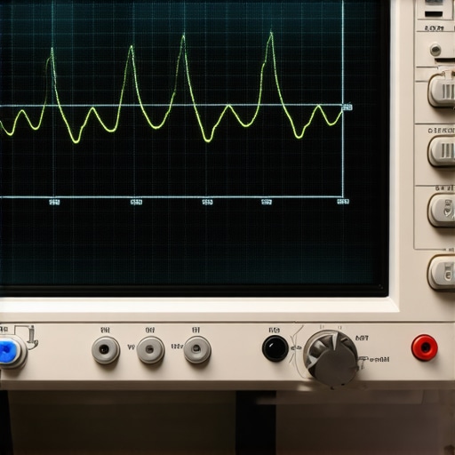
The gold standard for diagnosing an intermittent electrical fault is the digital storage oscilloscope (DSO). By backprobing the signal wire at the ECU connector, you can monitor the actual waveform in real-time. Set your scope to trigger on a falling edge and wiggle the wiring harness along its entire length. If you observe a dropped pulse or a collapsed voltage wave on your screen, you have found your physical fault spot. According to detailed signal analysis studies published by the Society of Automotive Engineers (SAE), electromagnetic interference from deteriorating alternator diodes can also corrupt the CKP signal, leading to false sensor fault codes when the sensor itself is completely functional.
If your diagnostic process reveals that your vehicle requires professional intervention or highly specialized equipment to resolve complex electrical anomalies, do not hesitate to contact our team of certified specialists for a comprehensive car service consultation today.
The Phantom Faults of Magnetic Interference and Shielding Breakdown
Beyond thermal drop-outs and wiring frays, a major cause of crankshaft sensor signal corruption lies in degraded electrical shielding. Hall-effect and variable reluctance sensors generate signals that are highly sensitive to external electromagnetic interference (EMI). Vehicle manufacturers wrap these sensor wires in a grounded foil or braided shield to block EMI from high-voltage components like spark plug wires, ignition coils, and the alternator. Over time, heat and engine vibration degrade this protective shield, allowing ignition noise to bleed into the CKP signal line. This causes the engine control unit to register erratic, extra crankshaft pulses that lead to violent engine bucking, random misfires, and sudden stalling.
When this shielding fails, the ECU often misinterprets the electrical noise as a physical engine malfunction. To determine if your issue is caused by EMI rather than a physical part failure, check the routing of your sensor harness to ensure it is not touching high-voltage ignition leads. If you are experiencing strange starting symptoms alongside these issues, you may also want to rule out other common electrical culprits by learning about the $12 fix for a car that is hard to start in the morning, which covers often-overlooked electrical bottlenecks.
Are You Chasing a Failed Sensor When the Real Culprit Is a Damaged Reluctor Ring?
Many technicians replace a crankshaft position sensor only to find the exact same driveability symptoms return within a few miles. When a new sensor fails to resolve the issue, the focus must shift to the mechanical trigger wheel, or reluctor ring, mounted on the crankshaft or balancer. This ring features a precise pattern of teeth and gaps that pass by the magnetic sensor tip. If a single tooth on this wheel is chipped, bent, or clogged with metallic road debris, the sensor will produce an irregular waveform at that exact rotational point. This creates a highly localized, consistent misfire or signal drop-out that no brand-new sensor can fix.
To inspect the trigger wheel without tearing down the front of the engine, you can use a digital inspection camera inserted through the sensor mounting hole. Manually rotate the engine crankshaft 360 degrees using a breaker bar on the harmonic balancer bolt, inspecting each tooth for damage or accumulated metallic debris. If the teeth are clean and undamaged, the root cause may lie elsewhere in your vehicle’s complex electrical architecture. For those dealing with baffling electrical symptoms, mastering a few diagnostic basics can save hours of frustration; we highly recommend reading about how to find a parasitic drain with a cheap multimeter to build your electrical troubleshooting confidence.
The Critical Role of Sensor Air Gap and Mounting Torque
For variable reluctance and non-adjustable Hall-effect sensors, the physical distance between the sensor tip and the face of the reluctor wheel—known as the air gap—is absolutely critical. A gap that is too wide weakens the magnetic field coupling, leading to a weak signal that fails completely at high RPMs. Conversely, an air gap that is too tight risks physical contact between the sensor and the spinning trigger wheel, which can destroy both components instantly. Many aftermarket sensors do not match original equipment specifications perfectly, resulting in minor dimensional differences that throw off this critical tolerance.
According to technical specifications published by the National Institute for Automotive Service Excellence (ASE), even a mounting bolt tightened just slightly out of specification can tilt the sensor body enough to skew the signal voltage. Always use a digital torque wrench to secure the sensor to the manufacturer’s exact specifications, and avoid using thick RTV silicone sealants on the mounting flange unless explicitly instructed, as this will artificially increase the air gap. Have you experienced a stubborn engine diagnostic issue that had you guessing? Leave a comment below with your symptoms, or share this guide with a fellow DIYer who is currently battling an elusive engine stall.
Decoding ECM Logic When Crankshaft and Camshaft Signals Desynchronize
When diagnostic trouble codes point toward a crankshaft position sensor error, master technicians know never to look at the CKP in isolation. Modern engine control modules continuously compare the crankshaft signal against the camshaft position (CMP) sensor signal to verify engine timing. This relationship, known as cam-crank synchronization, is the backbone of variable valve timing (VVT) and cylinder-specific ignition staging. If the timing chain stretches by as little as a fraction of an inch, or if a hydraulic tensioner loses pressure, the physical relationship between these two shafts drifts. The ECU detects this microscopic phase shift and, unable to determine which mechanical component is lying, often flags a generic CKP sensor malfunction code instead of a timing chain code.
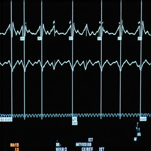
To diagnose this without tearing down the engine cover, you must perform a dual-channel scope capture. By probing both the camshaft and crankshaft sensor signals simultaneously, you can analyze the alignment of the trigger pulses. Referencing factory wave patterns allows you to see if the known-good synchronization alignment points have shifted. If the pulse relationship is skewing under load but remains stable at idle, the issue is likely a worn timing component or oil-starved VVT phasers rather than a sensor failure. For those dealing with complex under-hood systems, establishing a baseline of general maintenance is key; read about the essential steps of changing oil like a pro to ensure clean hydraulic pressure reaches your variable valve timing system.
Why Do Bad Engine Grounds Cause Ghost Crankshaft Position Sensor Codes?
Could a simple rusty bolt on the frame rail really cause your engine to stall and throw a crankshaft sensor code? Absolutely. The sensor ground is often shared inside the ECU with other high-current sensors and solenoids. If the primary engine-to-chassis ground strap degrades, the return current from larger electrical loads searches for the path of least resistance to get back to the battery. This current often back-feeds through the sensor ground circuit, raising the ground reference voltage above zero. When this ground float occurs, the square-wave signal generated by a Hall-effect sensor gets compressed, preventing the ECU from recognizing the voltage drops as timing pulses and triggering a false sensor failure code.
The Diagnostic Pitfalls of Cheap Aftermarket Replacements
The temptation to purchase budget-friendly aftermarket sensors is strong, but cheap components often introduce microscopic tolerance variations that confuse sensitive engine management systems. Original equipment manufacturers design these magnetic sensors with highly specific internal resistance profiles, coil winding counts, and rare-earth magnet strengths tailored to the specific electrical architecture of your vehicle. According to engineering standards verified by the Society of Automotive Engineers (SAE), cheaper replacement parts frequently fail to meet these exacting specifications, resulting in signal voltage decay at higher operating temperatures. If you want to keep your vehicle running reliably without risking roadside breakdowns, check out our diagnostic tools or speak with an expert directly on our car service contact page to source verified OEM parts for your specific vehicle model.
Analyzing Crankshaft Speed Fluctuations for Advanced Misfire Detection
Beyond simply telling the ECU when to spark, the crankshaft position sensor is also the primary tool used for misfire detection. As each cylinder fires, the crankshaft experiences a microscopic burst of acceleration. Conversely, when a cylinder misfires, the crankshaft momentarily decelerates during what should have been that cylinder’s power stroke. The ECU monitors these ultra-high-speed speed fluctuations using the CKP sensor’s signal frequency. If a sensor is slightly degraded, or if the reluctor wheel has minor runout, the ECU can no longer reliably calculate these micro-accelerations. This leads to erratic, false misfire codes across multiple random cylinders, prompting DIYers to waste hundreds of dollars on ignition coils and spark plugs when the root issue is signal resolution.
Why Weak Alternator Diodes Trigger Ghost Timing Codes
An often overlooked catalyst in the realm of engine management diagnostics is AC ripple voltage. When a diode within the alternator begins to degrade, it allows alternating current to leak directly into the vehicle’s 12-volt DC electrical system. While this minor AC voltage spike may not visibly affect the headlights or the radio, it plays havoc with the high-frequency digital signals returning from your crankshaft position sensor. The electromagnetic noise induced by this ripple voltage mimics the high-speed pulse wave of the CKP, causing the engine control unit to log phantom timing faults and initiate sudden, unexplained engine shutdowns.
To definitively diagnose this phenomenon, technicians must utilize the AC voltage setting on a digital multimeter or, ideally, a digital storage oscilloscope connected directly to the battery terminals. A healthy charging system should exhibit less than 0.5 volts of AC ripple. If your measurements exceed this threshold, the alternator is actively corrupting your timing signals. Understanding how electrical noise propagates through various subsystems is essential for accurate diagnostics; for broader issues with electrical starting systems, check out the specialized insights available at the Car Care Council to keep your vehicle starting reliably in all conditions.
Can Low Engine Oil Pressure Cause Fake Crankshaft Position Sensor Failures?
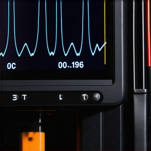
Yes, particularly in modern engines equipped with hydraulically actuated Variable Valve Timing (VVT) systems. These systems rely on precise oil pressure to advance or retard camshaft timing relative to the crankshaft. When oil pressure drops or becomes aerated due to a clogged pickup tube or incorrect oil viscosity, the VVT phasers fail to reach their targeted positions. The engine control unit detects this timing mismatch between the crankshaft and camshaft sensors and, because it lacks a physical sensor to measure mechanical chain slack directly, it frequently defaults to triggering a generic crankshaft position sensor circuit performance code.
The Complex Mechanics of High-RPM Signal Dropout
Another challenging scenario involves crankshaft sensor signals that perform flawlessly at idle but break down completely once the engine climbs past 4,000 RPM. This high-speed signal dropout is typically caused by a minor rotor runout or a slightly bent reluctor wheel. At low speeds, the magnetic field has sufficient time to recover between the teeth of the trigger wheel, maintaining a clean square wave. However, as the rotational speed increases, any microscopic wobble in the reluctor wheel compresses the time window for the magnetic field to collapse, resulting in a distorted waveform that the ECU can no longer interpret.
If you have spent hours troubleshooting erratic misfires and sensor dropouts without success, our experienced master technicians are here to help. Reach out to our team today for a tailored car service consultation to resolve your complex timing and electrical puzzles.
Expert Insights & Advanced Considerations
Look Beyond the Sensor for Signal Integrity
When dealing with complex engine management systems, a sensor code rarely guarantees a physically broken component. Master technicians must differentiate between a localized component failure and circuit voltage corruption. Standard multimeters often mask rapid voltage drops, meaning you must monitor signal returns in real time to capture fleeting disruptions before the ECM registers a permanent fault.
Why AC Ripple Voltage is Your Worst Enemy
Many diagnostic paths go cold because technicians ignore the vehicle’s charging system behavior. A failing alternator diode can bleed minor alternating current directly into the 12-volt DC circuitry. This electrical noise does not trip battery warning lights but can distort the high-frequency square wave of your CKP sensor, mimicking a physical component breakdown. Testing for AC ripple at the battery terminals is an essential, easy step that saves hours of pointless parts-swapping.
The Trap of Aftermarket Sensor Tolerances
Choosing budget-friendly aftermarket components often introduces microscopic deviations in internal winding resistance or magnetic pull. These discrepancies distort engine timing signals at elevated operating temperatures or high RPMs. To maintain structural integrity and prevent unexpected roadside failures, it is vital to source verified OEM parts that perfectly match your vehicle’s electronic profile.
Curated Expert Resources
For those looking to deepen their automotive diagnostic capabilities, several professional platforms offer invaluable technical documentation:
- Society of Automotive Engineers (SAE) Technical Library: Access in-depth engineering papers detailing signal-to-noise ratio requirements and electromagnetic interference shielding specifications.
- National Institute for Automotive Service Excellence (ASE): Leverage their standardized training materials and testing procedures to refine your systematic electrical diagnostic approach.
- The Car Care Council: Provides excellent consumer education materials to understand how complex electrical subsystems affect overall vehicle longevity.
Final Expert Perspective
Conquering the elusive ghost of a crankshaft position sensor failure requires a transition from basic parts-swapping to rigorous, waveform-based diagnostics. Intermittent stalling, high-RPM dropouts, and phantom misfires are rarely simple issues; they are the result of complex interactions between thermal stress, electromagnetic interference, and precise mechanical tolerances. By looking at the complete electrical environment—from charging system health to ground loop integrity—you can resolve diagnostic mysteries that leave lesser shops scratching their heads. If you are currently chasing a stubborn driveability puzzle or want to optimize your engine management systems, explore our specialized diagnostic guides on vehicle diagnostics, or reach out to our team via our car service contact page to consult directly with a master technician today.