Modern Ignition Systems Demand More Than High-Level Scanners
In the contemporary landscape of auto repair, the reliance on On-Board Diagnostics (OBD-II) has created a generation of technicians who often overlook the fundamental physics of the internal combustion engine. While a scan tool can point toward a cylinder-specific misfire, it frequently fails to differentiate between a failing spark plug, a compromised fuel injector, or a deteriorating ignition coil. To achieve true vehicle diagnostics mastery, one must return to the basics of electrical resistance and dielectric strength. Assessing the secondary ignition circuit requires more than just reading data pids; it requires a physical stress test of the coil’s ability to generate sufficient voltage to ionize the air-fuel mixture under compression. This is where the simple spark plug tool—specifically a calibrated spark gap tester—becomes an indispensable asset in any professional car service environment.
Why Digital Data Often Masks Intermittent Misfires
The Engine Control Module (ECM) monitors misfires primarily through crankshaft position sensor fluctuations. However, an ignition coil that is beginning to suffer from internal shorting or insulation breakdown may still function adequately at idle or low-load conditions. These ‘ghost’ issues often go undetected by standard diagnostics until they reach a critical failure point. Understanding the hidden world of vehicle diagnostics reveals that analog tools provide real-time visual confirmation of spark intensity that a computer simply cannot replicate. By forcing the coil to jump a predetermined gap, we simulate the increased resistance found within the combustion chamber during high-load scenarios.
The Physics of the Spark Gap Test
To test a coil pack effectively, you must understand the relationship between voltage and air resistance. According to Paschen’s Law, the voltage required to create a spark across a gap is a function of the pressure and the gap distance. In a pressurized cylinder, the voltage requirement spikes significantly. A healthy coil should easily jump a 20kV to 30kV gap in open air to ensure it can overcome the 10kV to 15kV required under the high-pressure environment of an active engine. If your engine is struggling, it may be because of the 20-spark fix that addresses these precise voltage drops.
How can you tell if a coil is breaking down under load?
The definitive test involves connecting the spark gap tool between the coil output and a known good ground. Set the gap to the manufacturer’s high-stress specification—usually around 30,000 volts (30kV). Crank the engine and observe the spark’s color and consistency. A strong, healthy coil produces a crisp, bright blue snap. A failing coil will produce a thin, yellowish spark, or may fail to jump the gap entirely as the energy finds an easier path to ground through internal cracks in the coil’s housing. This physical verification is more reliable than even some advanced paperclip fault code hacks used for older systems.
Executing the Stress Test with Precision
When performing this diagnostic, safety and precision are paramount. High-energy ignition systems can deliver a painful, if not dangerous, electrical shock. Always use insulated tools and ensure no flammable vapors are present in the engine bay. For those managing more complex issues beyond the ignition system, such as transmission irregularities or shift-point errors, integrating these manual testing methods with electronic data remains the gold standard for comprehensive maintenance. If you are looking to elevate your DIY capabilities, exploring our guide on expert auto repair tips for 2025 will provide the technical depth needed to tackle modern automotive challenges. For professional assistance with complex electrical or mechanical failures, feel free to contact us for expert guidance.
Ignition Failures Frequently Masquerade as Transmission Trouble
Many drivers report a rhythmic shudder at highway speeds, immediately assuming a failing torque converter or a fluid issue. However, a weak ignition coil operating under high-load, low-RPM conditions often creates a sensation nearly identical to a mechanical transmission slip. This diagnostic overlap is why transmission failures decoded by experts always prioritize a secondary ignition health check. Before you reach for the 5-additive that stopped our shop’s worst transmission shudder, you must ensure your coils aren’t the culprit. When the engine underperforms, the Transmission Control Module (TCM) receives inconsistent torque data, leading to erratic shift patterns that can deceive even seasoned technicians into recommending expensive and unnecessary gearbox repairs.
Can your scan tool actually visualize the breakdown of dielectric strength?
While modern OBD-II interfaces are powerful, they are essentially historians, not real-time observers of electrical physics. A scan tool tells you what happened a millisecond ago based on software interpretations, but it cannot see the literal bridge of electricity failing across a hairline fracture in a coil boot. The Society of Automotive Engineers (SAE) notes that combustion instability often correlates with erratic secondary voltage patterns, which can trick the engine control module into making incorrect fuel trim adjustments. This results in ‘ghosting’ errors where sensors appear faulty when the root cause is actually poor spark saturation. To combat this, technicians should learn to identify 2026 sensor ghosting errors through manual logic rather than blind trust in a code reader.
Identify Voltage Leaks Before They Kill Your ECM
Carbon tracking is a silent killer in high-energy ignition systems. It occurs when a spark finds a path along the surface of the insulator rather than jumping the gap of the plug. This creates a permanent, conductive trail of carbon that steals energy from the combustion process. If left unaddressed, this parasitic draw can eventually feedback into the primary circuit, potentially damaging the sensitive drivers within the Engine Control Module. Identifying these microscopic tracks requires a keen eye and often a high-intensity light. 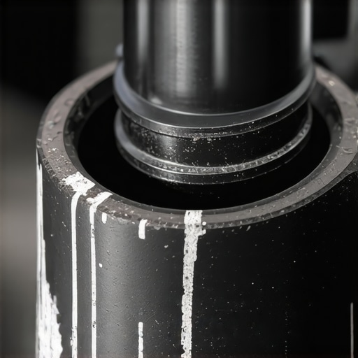 If you notice a thin, jagged white or black line on the ceramic of a spark plug or the inside of a rubber boot, you have found your leak. These issues are frequently the cause when a vehicle starts to stumble at stoplights, appearing like a vacuum leak but behaving with the unpredictability of an electrical short.
Vary Your Testing Routine to Catch Thermal Failures
Coils are notorious for failing only when they reach a specific operating temperature. The internal copper windings expand as they heat up, which can cause a hairline break in the wire to open and break the circuit. This is why a car may run perfectly for twenty minutes and then suddenly develop a dead misfire. Mastering these nuances separates the ‘parts changers’ from the diagnostic experts. By integrating thermal imaging or simple heat-gun simulation into your workflow, you can force these failures to manifest in the bay rather than during a customer’s commute. If you want to refine your approach further, exploring top auto repair techniques will help you bridge the gap between basic maintenance and advanced troubleshooting. Have you ever spent days chasing a code only to find a 10-cent crack in a plastic housing? Share your most difficult diagnostic ‘save’ in the comments below.
Capture the Waveform to See What Your Scan Tool Misses
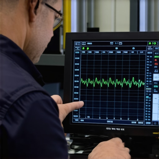
While the spark gap tester provides a binary ‘yes/no’ on coil strength, the digital storage oscilloscope (DSO) offers a granular look into the heart of the combustion event. A scan tool displays processed data, but a scope captures the raw electrical signature of the ignition strike. By analyzing the ignition secondary waveform, an expert technician can observe the ‘burn time’—the actual duration the spark exists across the plug gap. A healthy burn line should be clean and horizontal; a line that slopes upward or ends prematurely indicates high resistance or a lean air-fuel mixture. This level of vehicle diagnostics is essential because it reveals the chemical environment inside the cylinder without ever removing a bolt. If the burn time is less than 0.8 milliseconds, you are looking at a system that cannot sustain combustion, likely leading to the transmission hunting issues discussed earlier.
Does an upgraded ignition coil actually boost horsepower?
In the world of auto repair and performance tuning, there is a common misconception that high-output coils create more power. In reality, a coil only delivers the energy required to overcome the resistance of the gap. If your engine requires 12kV to fire and you install a 50kV coil, it will still only fire at 12kV. The benefit of ‘performance’ coils lies in their ‘reserve’ voltage—the ability to maintain a spark under extreme cylinder pressures found in turbocharged or high-compression builds. According to research published in the SAE International Journal of Engines (Technical Paper 2018-01-1132), the stability of the ignition delay period is the primary driver of torque consistency. Unless your current coils are failing to bridge the gap under load, a ‘hotter’ coil is rarely a magic bullet for speed, though it does provide a wider safety margin against high-RPM blow-out.
Boost Pressure vs. Spark Strength: The Hidden Combat Inside Your Cylinders
As modern car service increasingly involves small-displacement turbocharged engines, the demand on the ignition system has doubled. Turbocharging forces more air and fuel into the same space, effectively increasing the density of the medium the spark must punch through. This increased density acts as a massive electrical insulator. A coil that works perfectly at atmospheric pressure may fail instantly under 15 psi of boost. This is why gap specifications have shrunk from the 0.060″ seen in the 1990s to as tight as 0.028″ in modern GDI (Gasoline Direct Injection) engines. Tightening the gap reduces the voltage required to fire, which protects the coil from internal dielectric breakdown but requires a more precise, high-energy pulse to ensure complete combustion.
The Grounding Trap That Fools Even Master Techs
You can have the most expensive coil and the finest iridium plugs, but if the engine ground strap is corroded, the secondary circuit will struggle. The spark travels from the coil, through the plug, and must return through the engine block to the battery. Resistance on the ground side of the circuit creates ‘electrical noise’ that can interfere with sensitive vehicle diagnostics sensors like the Crankshaft Position (CKP) or Camshaft Position (CMP) sensors. This high-frequency interference often triggers false codes for sensor failure when the real culprit is a rusted bolt on the frame rail. Before replacing expensive electronics, always perform a voltage drop test on the engine’s main grounding points to ensure the return path is as clear as the delivery path.
Stop Chasing Ghost Codes by Understanding Coil Saturation
Every ignition coil requires a specific ‘dwell time’—the duration the primary circuit is closed to allow the magnetic field to build. If the ECM commands a dwell time that is too short, the coil never reaches full saturation, resulting in a weak spark. Conversely, excessive dwell time leads to overheating and premature coil failure. In many cases, aftermarket ‘budget’ coils have different winding resistances than OEM units, leading to saturation mismatches that the ECM cannot compensate for. This mismatch is a frequent cause of the rhythmic hesitations that owners mistake for transmission slip or fuel pump failure. When choosing parts, the ‘cheap’ option often ends up being the most expensive after you factor in the diagnostic hours spent chasing the resulting intermittent misfires. As we look toward the future of auto repair, the integration of smart-coils with built-in ion sensing is beginning to change the game once again by…
…turning the spark plug itself into a real-time combustion sensor. This technology, often referred to as ion-current sensing, uses the gap as a probe. By applying a small bias voltage across the gap after the spark event, the Engine Control Module (ECM) measures the conductivity of the ionized gases. This allows for cylinder-by-cylinder monitoring of the pressure peak, effectively eliminating the need for traditional knock sensors. In a high-end auto repair facility, recognizing these systems is vital because a simple plug change to a non-resistor type can completely blind the ECM to its own combustion health, leading to aggressive timing retards and phantom power loss.
Unmasking the Combustion Process Through Ion-Current Data
When the spark plug transitions from an igniter to a sensor, the level of vehicle diagnostics reaches a molecular level. The ion-current signal provides a high-resolution map of the chemical reactions within the chamber. If the signal is weak or delayed, it suggests a lean-out condition or poor fuel atomization that a standard oxygen sensor—averaging data from multiple cylinders—would likely miss. For technicians focused on elite car service, this data is the difference between guessing and knowing. By analyzing the ‘post-fire’ ionization phase, you can detect pre-ignition events long before they cause audible knock or mechanical damage to the piston crowns.
Can the spark plug itself act as a laboratory-grade combustion sensor?
Yes, in modern ion-sensing systems, the spark plug serves as a transducer that provides real-time feedback on peak pressure timing. This allows the ECM to adjust ignition timing for the very next cycle, maximizing thermal efficiency and torque output without relying solely on vibration-based knock sensors. Mastering this interpretation is a hallmark of top-tier auto repair in the 2020s. For deep technical insights on electromagnetic compatibility and sensor integration in automotive environments, the technical resources at Delphi Technologies offer peer-reviewed data on how ignition frequency affects modular communication and signal integrity.
Neutralize the EMI Storm Before It Paralyzes the TCM
Electromagnetic interference (EMI) is the silent enemy of the modern digital nervous system. When an ignition coil has an internal short or a leaking boot, it doesn’t just cause a misfire; it broadcasts a radio-frequency storm. This ‘noise’ can bleed into the unshielded wires of the CAN-bus network, corrupting the packets of data sent between the engine and the transmission controller. This is often why a ‘ghost’ code for a gear ratio error or a shift solenoid failure appears when the root cause is actually a secondary ignition leak. 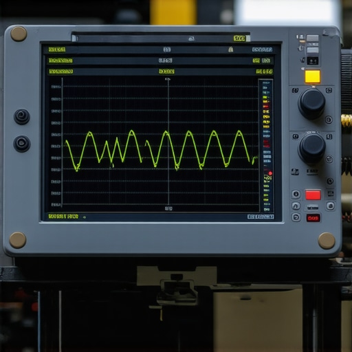 These spikes of interference can induce false voltages in sensor return lines, tricking the computer into thinking a mechanical slip is occurring.
Master the Art of Primary Current Ramping
While voltage measurements show what the coil *wants* to do, current ramping shows what the coil is *actually* doing. Using a low-amp probe around the primary wire, a technician can see the ‘turn-on’ point and the ‘saturation’ curve. If the ramp is too steep, the coil has shorted windings, reducing its inductive capacity. If the ramp is too shallow, the primary circuit has excessive resistance, often due to a corroded connector or a failing driver in the ECM. This level of precision ensures that you aren’t just swapping parts but diagnosing the atomic-level failure of the component. If you have encountered a ‘ghost’ transmission error that vanished after a simple coil swap, share your diagnostic journey in the comments below to help others in the community navigate these complex electrical puzzles.
Modern Ignition Systems Demand More Than High-Level Scanners
In the contemporary landscape of auto repair, the reliance on On-Board Diagnostics (OBD-II) has created a generation of technicians who often overlook the fundamental physics of the internal combustion engine. While a scan tool can point toward a cylinder-specific misfire, it frequently fails to differentiate between a failing spark plug, a compromised fuel injector, or a deteriorating ignition coil. To achieve true vehicle diagnostics mastery, one must return to the basics of electrical resistance and dielectric strength. Assessing the secondary ignition circuit requires more than just reading data pids; it requires a physical stress test of the coil’s ability to generate sufficient voltage to ionize the air-fuel mixture under compression. This is where the simple spark plug tool—specifically a calibrated spark gap tester—becomes an indispensable asset in any professional car service environment.
Why Digital Data Often Masks Intermittent Misfires
The Engine Control Module (ECM) monitors misfires primarily through crankshaft position sensor fluctuations. However, an ignition coil that is beginning to suffer from internal shorting or insulation breakdown may still function adequately at idle or low-load conditions. These ‘ghost’ issues often go undetected by standard diagnostics until they reach a critical failure point. Understanding the hidden world of vehicle diagnostics reveals that analog tools provide real-time visual confirmation of spark intensity that a computer simply cannot replicate. By forcing the coil to jump a predetermined gap, we simulate the increased resistance found within the combustion chamber during high-load scenarios.
The Physics of the Spark Gap Test
To test a coil pack effectively, you must understand the relationship between voltage and air resistance. According to Paschen’s Law, the voltage required to create a spark across a gap is a function of the pressure and the gap distance. In a pressurized cylinder, the voltage requirement spikes significantly. A healthy coil should easily jump a 20kV to 30kV gap in open air to ensure it can overcome the 10kV to 15kV required under the high-pressure environment of an active engine. If your engine is struggling, it may be because of the 20-spark fix that addresses these precise voltage drops.
How can you tell if a coil is breaking down under load?
The definitive test involves connecting the spark gap tool between the coil output and a known good ground. Set the gap to the manufacturer’s high-stress specification—usually around 30,000 volts (30kV). Crank the engine and observe the spark’s color and consistency. A strong, healthy coil produces a crisp, bright blue snap. A failing coil will produce a thin, yellowish spark, or may fail to jump the gap entirely as the energy finds an easier path to ground through internal cracks in the coil’s housing. This physical verification is more reliable than even some advanced paperclip fault code hacks used for older systems.
Executing the Stress Test with Precision
When performing this diagnostic, safety and precision are paramount. High-energy ignition systems can deliver a painful, if not dangerous, electrical shock. Always use insulated tools and ensure no flammable vapors are present in the engine bay. For those managing more complex issues beyond the ignition system, such as transmission irregularities or shift-point errors, integrating these manual testing methods with electronic data remains the gold standard for comprehensive maintenance. If you are looking to elevate your DIY capabilities, exploring our guide on expert auto repair tips for 2025 will provide the technical depth needed to tackle modern automotive challenges. For professional assistance with complex electrical or mechanical failures, feel free to contact us for expert guidance.
Ignition Failures Frequently Masquerade as Transmission Trouble
Many drivers report a rhythmic shudder at highway speeds, immediately assuming a failing torque converter or a fluid issue. However, a weak ignition coil operating under high-load, low-RPM conditions often creates a sensation nearly identical to a mechanical transmission slip. This diagnostic overlap is why transmission failures decoded by experts always prioritize a secondary ignition health check. Before you reach for the 5-additive that stopped our shop’s worst transmission shudder, you must ensure your coils aren’t the culprit. When the engine underperforms, the Transmission Control Module (TCM) receives inconsistent torque data, leading to erratic shift patterns that can deceive even seasoned technicians into recommending expensive and unnecessary gearbox repairs.
Can your scan tool actually visualize the breakdown of dielectric strength?
While modern OBD-II interfaces are powerful, they are essentially historians, not real-time observers of electrical physics. A scan tool tells you what happened a millisecond ago based on software interpretations, but it cannot see the literal bridge of electricity failing across a hairline fracture in a coil boot. The Society of Automotive Engineers (SAE) notes that combustion instability often correlates with erratic secondary voltage patterns, which can trick the engine control module into making incorrect fuel trim adjustments. This results in ‘ghosting’ errors where sensors appear faulty when the root cause is actually poor spark saturation. To combat this, technicians should learn to identify 2026 sensor ghosting errors through manual logic rather than blind trust in a code reader.
Identify Voltage Leaks Before They Kill Your ECM
Carbon tracking is a silent killer in high-energy ignition systems. It occurs when a spark finds a path along the surface of the insulator rather than jumping the gap of the plug. This creates a permanent, conductive trail of carbon that steals energy from the combustion process. If left unaddressed, this parasitic draw can eventually feedback into the primary circuit, potentially damaging the sensitive drivers within the Engine Control Module. Identifying these microscopic tracks requires a keen eye and often a high-intensity light. If you notice a thin, jagged white or black line on the ceramic of a spark plug or the inside of a rubber boot, you have found your leak. These issues are frequently the cause when a vehicle starts to stumble at stoplights, appearing like a vacuum leak but behaving with the unpredictability of an electrical short.
Vary Your Testing Routine to Catch Thermal Failures
Coils are notorious for failing only when they reach a specific operating temperature. The internal copper windings expand as they heat up, which can cause a hairline break in the wire to open and break the circuit. This is why a car may run perfectly for twenty minutes and then suddenly develop a dead misfire. Mastering these nuances separates the ‘parts changers’ from the diagnostic experts. By integrating thermal imaging or simple heat-gun simulation into your workflow, you can force these failures to manifest in the bay rather than during a customer’s commute. If you want to refine your approach further, exploring top auto repair techniques will help you bridge the gap between basic maintenance and advanced troubleshooting. Have you ever spent days chasing a code only to find a 10-cent crack in a plastic housing? Share your most difficult diagnostic ‘save’ in the comments below.
Capture the Waveform to See What Your Scan Tool Misses
While the spark gap tester provides a binary ‘yes/no’ on coil strength, the digital storage oscilloscope (DSO) offers a granular look into the heart of the combustion event. A scan tool displays processed data, but a scope captures the raw electrical signature of the ignition strike. By analyzing the ignition secondary waveform, an expert technician can observe the ‘burn time’—the actual duration the spark exists across the plug gap. A healthy burn line should be clean and horizontal; a line that slopes upward or ends prematurely indicates high resistance or a lean air-fuel mixture. This level of vehicle diagnostics is essential because it reveals the chemical environment inside the cylinder without ever removing a bolt. If the burn time is less than 0.8 milliseconds, you are looking at a system that cannot sustain combustion, likely leading to the transmission hunting issues discussed earlier.
Does an upgraded ignition coil actually boost horsepower?
In the world of auto repair and performance tuning, there is a common misconception that high-output coils create more power. In reality, a coil only delivers the energy required to overcome the resistance of the gap. If your engine requires 12kV to fire and you install a 50kV coil, it will still only fire at 12kV. The benefit of ‘performance’ coils lies in their ‘reserve’ voltage—the ability to maintain a spark under extreme cylinder pressures found in turbocharged or high-compression builds. According to research published in the SAE International Journal of Engines (Technical Paper 2018-01-1132), the stability of the ignition delay period is the primary driver of torque consistency. Unless your current coils are failing to bridge the gap under load, a ‘hotter’ coil is rarely a magic bullet for speed, though it does provide a wider safety margin against high-RPM blow-out.
Boost Pressure vs. Spark Strength: The Hidden Combat Inside Your Cylinders
As modern car service increasingly involves small-displacement turbocharged engines, the demand on the ignition system has doubled. Turbocharging forces more air and fuel into the same space, effectively increasing the density of the medium the spark must punch through. This increased density acts as a massive electrical insulator. A coil that works perfectly at atmospheric pressure may fail instantly under 15 psi of boost. This is why gap specifications have shrunk from the 0.060″ seen in the 1990s to as tight as 0.028″ in modern GDI (Gasoline Direct Injection) engines. Tightening the gap reduces the voltage required to fire, which protects the coil from internal dielectric breakdown but requires a more precise, high-energy pulse to ensure complete combustion.
The Grounding Trap That Fools Even Master Techs
You can have the most expensive coil and the finest iridium plugs, but if the engine ground strap is corroded, the secondary circuit will struggle. The spark travels from the coil, through the plug, and must return through the engine block to the battery. Resistance on the ground side of the circuit creates ‘electrical noise’ that can interfere with sensitive vehicle diagnostics sensors like the Crankshaft Position (CKP) or Camshaft Position (CMP) sensors. This high-frequency interference often triggers false codes for sensor failure when the real culprit is a rusted bolt on the frame rail. Before replacing expensive electronics, always perform a voltage drop test on the engine’s main grounding points to ensure the return path is as clear as the delivery path.
Stop Chasing Ghost Codes by Understanding Coil Saturation
Every ignition coil requires a specific ‘dwell time’—the duration the primary circuit is closed to allow the magnetic field to build. If the ECM commands a dwell time that is too short, the coil never reaches full saturation, resulting in a weak spark. Conversely, excessive dwell time leads to overheating and premature coil failure. In many cases, aftermarket ‘budget’ coils have different winding resistances than OEM units, leading to saturation mismatches that the ECM cannot compensate for. This mismatch is a frequent cause of the rhythmic hesitations that owners mistake for transmission slip or fuel pump failure. When choosing parts, the ‘cheap’ option often ends up being the most expensive after you factor in the diagnostic hours spent chasing the resulting intermittent misfires. As we look toward the future of auto repair, the integration of smart-coils with built-in ion sensing is beginning to change the game once again by turning the spark plug itself into a real-time combustion sensor. This technology, often referred to as ion-current sensing, uses the gap as a probe. By applying a small bias voltage across the gap after the spark event, the Engine Control Module (ECM) measures the conductivity of the ionized gases. This allows for cylinder-by-cylinder monitoring of the pressure peak, effectively eliminating the need for traditional knock sensors. In a high-end auto repair facility, recognizing these systems is vital because a simple plug change to a non-resistor type can completely blind the ECM to its own combustion health, leading to aggressive timing retards and phantom power loss.
Unmasking the Combustion Process Through Ion-Current Data
When the spark plug transitions from an igniter to a sensor, the level of vehicle diagnostics reaches a molecular level. The ion-current signal provides a high-resolution map of the chemical reactions within the chamber. If the signal is weak or delayed, it suggests a lean-out condition or poor fuel atomization that a standard oxygen sensor—averaging data from multiple cylinders—would likely miss. For technicians focused on elite car service, this data is the difference between guessing and knowing. By analyzing the ‘post-fire’ ionization phase, you can detect pre-ignition events long before they cause audible knock or mechanical damage to the piston crowns.
Can the spark plug itself act as a laboratory-grade combustion sensor?
Yes, in modern ion-sensing systems, the spark plug serves as a transducer that provides real-time feedback on peak pressure timing. This allows the ECM to adjust ignition timing for the very next cycle, maximizing thermal efficiency and torque output without relying solely on vibration-based knock sensors. Mastering this interpretation is a hallmark of top-tier auto repair in the 2020s. For deep technical insights on electromagnetic compatibility and sensor integration in automotive environments, the technical resources at Delphi Technologies offer peer-reviewed data on how ignition frequency affects modular communication and signal integrity.
Neutralize the EMI Storm Before It Paralyzes the TCM
Electromagnetic interference (EMI) is the silent enemy of the modern digital nervous system. When an ignition coil has an internal short or a leaking boot, it doesn’t just cause a misfire; it broadcasts a radio-frequency storm. This ‘noise’ can bleed into the unshielded wires of the CAN-bus network, corrupting the packets of data sent between the engine and the transmission controller. This is often why a ‘ghost’ code for a gear ratio error or a shift solenoid failure appears when the root cause is actually a secondary ignition leak. #IMAGE_PLACE_HOLDER_D# These spikes of interference can induce false voltages in sensor return lines, tricking the computer into thinking a mechanical slip is occurring.
Master the Art of Primary Current Ramping
While voltage measurements show what the coil wants to do, current ramping shows what the coil is actually doing. Using a low-amp probe around the primary wire, a technician can see the ‘turn-on’ point and the ‘saturation’ curve. If the ramp is too steep, the coil has shorted windings, reducing its inductive capacity. If the ramp is too shallow, the primary circuit has excessive resistance, often due to a corroded connector or a failing driver in the ECM. This level of precision ensures that you aren’t just swapping parts but diagnosing the atomic-level failure of the component. If you have encountered a ‘ghost’ transmission error that vanished after a simple coil swap, share your diagnostic journey in the comments below to help others in the community navigate these complex electrical puzzles.
Expert Insights & Advanced Considerations
Why Coils Fail Only When You Push the Pedal
The relationship between cylinder pressure and dielectric strength is a critical variable. As you increase throttle, you increase air density, which effectively acts as a thicker insulator for the spark to penetrate. A coil that appears healthy on a multi-meter or at idle can fail instantly under load. This is why a physical stress test is non-negotiable for professional vehicle diagnostics.
How Ignition Ghosting Ruins Gearbox Logic
When an ignition coil leaks energy, it creates electromagnetic interference that can corrupt the CAN-bus signals intended for the Transmission Control Module. This leads to harsh shifting or ‘hunting’ for gears. Before assuming you need a rebuild, consult expert analysis to rule out these electrical ghosts.
Your Spark Plug Is Now a Laboratory Sensor
Ion-current sensing technology turns the combustion chamber into a live data feed. By measuring the conductivity of the air-fuel mixture after the spark, the engine computer can detect knock or lean conditions with microscopic precision. This evolution in car service technology requires technicians to use specific OEM-grade plugs to maintain signal integrity.
Curated Expert Resources
SAE International Technical Papers are the gold standard for understanding the physics of ignition delay and combustion stability. These documents provide the raw data that informs modern engine management strategies.
Delphi Technologies OEM Training provides deep-dives into fuel system integration and modular ignition design. This is essential for those looking to master choosing the right car service for technical repairs.
The Pico Technology Waveform Library is an indispensable database of known-good and known-bad ignition waveforms. It allows technicians to compare real-time data against thousands of verified vehicle captures.
Final Expert Perspective
Mastering the intricacies of the secondary ignition circuit is what separates a technician from a hobbyist. By combining the raw visual data of a spark gap test with the high-resolution electrical signatures of an oscilloscope, you can achieve a level of vehicle diagnostics that scan tools simply cannot match. This approach doesn’t just fix the car—it protects the expensive electronic brain of the vehicle from parasitic damage. If you are ready to take the next step in your technical journey, check out our expert auto repair tips for 2025 or contact us to discuss complex diagnostic solutions with our team.